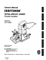
Craftsman 315.175500, Owner'S Manual
The Craftsman 315.175500 Owner's Manual is a must-have for any DIY enthusiast. With this manual, you can easily navigate through the installation, troubleshooting, and maintenance procedures. Download your free copy from our website manualshive.com and unleash your crafting potential effortlessly.
Share
Download


Reviews:
No comments
Related manuals for 315.175500

RF100/710
Brand: Felisatti Pages: 53
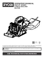
EBJ720K
Brand: Ryobi Pages: 24
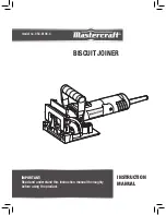
054-8106-4
Brand: MasterCraft Pages: 12

BBJ9000
Brand: BorMann Pages: 25
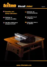
BJA 300
Brand: Triton Pages: 9
Top 21
Brand: Lamello Pages: 120
96 30 49
Brand: Westfalia Pages: 28
38648
Brand: Chicago Electric Pages: 14
PFDFA 20-Li A1
Brand: Parkside Pages: 179
17539 - 6.0 Amp Plate Jointer
Brand: Craftsman Pages: 26

DW682K
Brand: DeWalt Pages: 64
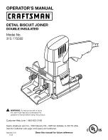
17550 - 3.5 Amp Detail Biscuit Jointer
Brand: Craftsman Pages: 26
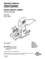
315.175501
Brand: Craftsman Pages: 24

BM018
Brand: 909 Pages: 16
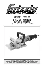
T31999
Brand: Grizzly Pages: 32
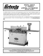
G0490X
Brand: Grizzly Pages: 2
G0490
Brand: Grizzly Pages: 68
BJK-1010U
Brand: Ozito Pages: 10


