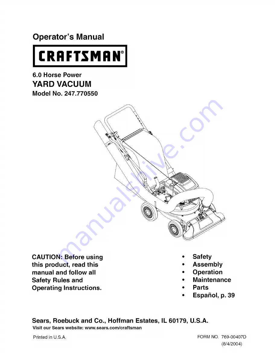
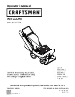
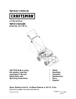
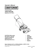
Craftsman 247-770550, Operator'S Manual
The Craftsman 247-770550 Operator's Manual is a comprehensive guide essential for operating and maintaining your machine. It is available for free download at manualshive.com. This manual provides detailed instructions and helpful tips, ensuring a smooth and efficient user experience for your Craftsman 247-770550 product.
Share
Download

Reviews:
No comments
Related manuals for 247-770550
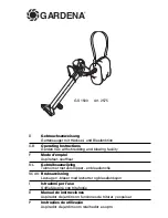
GS 1500
Brand: Gardena Pages: 11
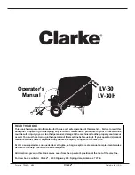
ALTO LV-30
Brand: Clarke Pages: 14
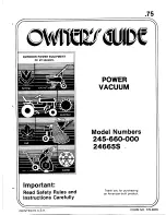
245-660-000
Brand: MTD Pages: 12
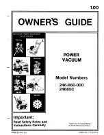
246-660-000
Brand: MTD Pages: 12
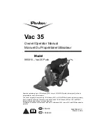
995810-Vac 35 Push
Brand: Parker Pages: 20
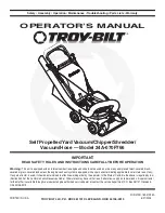
24A-070F768
Brand: Troy-Bilt Pages: 24
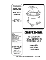
113.170340
Brand: Craftsman Pages: 16
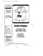
113.177630
Brand: Craftsman Pages: 16
113.177920
Brand: Craftsman Pages: 16
113.179100
Brand: Craftsman Pages: 44
247.77003
Brand: Craftsman Pages: 48

247.77010
Brand: Craftsman Pages: 60
247.77011
Brand: Craftsman Pages: 40
247.770110
Brand: Craftsman Pages: 40
247.77012
Brand: Craftsman Pages: 60
247.770120
Brand: Craftsman Pages: 60
247.77013.0
Brand: Craftsman Pages: 64
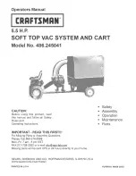
486.245041 Operators
Brand: Craftsman Pages: 28


