background image

Summary of Contents for 183.172521

Page 1: ...tool body while operating Never operate the tool by holding only the tool handle CAUTION Before using this Cutting Tool read this manual and follow all its Safety Rules and Operating Instructions Safety Instructions Accessories Assembly Operation Maintenance Parts List Espanol Sears Roebuck and Co Hoffman Estates IL 60179 USA Part No 183172520003 Rev 3 06 27 02 ...

Page 2: ... Some examples of these chemicals are Lead from lead based paints Crystalline silica from bricks cement and other masonry products Arsenic and chromium from chemically treated lumber Your risk from these exposures varies depending on how often you do this type of work To reduce your expos to these chemicals work in a well ventilated area and work with approved safety equipment such as those dust m...

Page 3: ...ing parts Non slip footwear is recommended Wear protective hair covering to contain long hair 23 MAINTAIN TOOLS WITH CARE Keep tools sharp and clean for most efficient and safest performance Follow instructions for lubricating and changing accessories CHECK FOR DAMAGED PARTS Before further use of the tool a guard or other part that is damaged should be carefully checked to ensure itwill operate pr...

Page 4: ...ORKPIECE TO HOLD IT STEADY WHEN CUTTING This will free both hands for operating the tool 11 12 13 14 15 16 17 18 19 20 NEVER HOLD THE WORKPIECE IN ONE HAND while operating the tool with the other hand NEVER PLACE HANDS IN THE PATH OF THE CU I rER AND UNDER THE WORKPIECE NEVER START THE TOOL WHEN THE BIT IS TOUCHING THE WORKPIECE The bit may catch the workpiece causing loss of control ALWAYS HOLD T...

Page 5: ...xtension cord is In good condition When using an extension card be sure to use one heavy enough to carry the current the tool will draw An undersized cord will cause a drop in line voltage resulting in loss of power and overheating The table below shows the correct size to use according to cord length and nameplate ampere rating If in doubt use the next heavier gauge The smaller the gauge number t...

Page 6: ...d assembly is complet Carefully unpack the cutting tool and all its components Compare against the Cutting Tool Components chart below NOTE See Page 7 for illustration of components I_ WARNING I To avoid fire or toxic reaction never use gasoline naphtha acetone lacquer thinner or similar highly volatile solvents to clean the cutting toot CUTTING TOOL COMPONENTS KEY _ DESCRIPTION Inside Carrying Ca...

Page 7: ... K E ...

Page 8: ...ob Lever Locking Knob Circle Cutting Quick Lever Moungng Inse_ Mounting Bracket Disc _ Precision Handle Motor Housing Lockin Lever Sole _ Plate Motor Housing t Lockinl Knob Router Base Depth Stop Rod Height Adjus_ng Knobs Plunge Action Tu_et Bevel Adjusting Lock ...

Page 9: ... control switch 2 away from the ON OFF switch 4 To set the speed control switch to low speed slide the speed control switch 2 toward the ON OFF switch INSTALLING CUTTING BITS I A WARNING I Cutting bit and router bit cutting surfaces are extremely sharp Handle with caution To insert a cutting bit use the collet wrench which is in the wrench holder attached to the power cord 2 Depress the shaft lock...

Page 10: ...is designed for basic freehand cutting with the cutting bit It is ideally suited for cutting electrical outlet holes in dr wall IA WARNINGI Do NOT use the freehand sole plate with router bits Limited control with this accessory could cause you to loose control and inc_ase the chance of serious injury INSTALLING FREEHAND SOLE PLATE cont d Slide freehand sole plate mounting bracket 1 on the bottom o...

Page 11: ...ist Fig 6 PRACTICE CUTS USING FREEHAND SOLE PLATE 6 Set the speed control switch to the appropriate speed 7 Turn the switch ON When the motor is up to full speed slowly tip the tool to an upright position letting the bit cut into the workpiece see Fig 7 Once the tool has reached the upright position and the bit has cut through the workpiece slowly move the tool in a clockwise direction using slow ...

Page 12: ... install freehand sole plate as outlined on Pages 9 10 of this Owner s Manual Adjust depth of cut so the bit will protrude 1 8 beyond the thickness of the drywall Hold the tool firmly with both hands and turn it ON Plunge the bit through the drywall at the mark indicating the center of the box See Fig 8 for cutting pattern Fig 8 cu n ING OUTLET OPENINGS IN DRYWALL con_ 6 7 Move the bit slowly to t...

Page 13: ...epth make sure sole plate is at right angles to the bit and securely tightened Re check the coltet to make sure the bit is securely fastened ADJUSTING FREEHAND SOLE PLATE Cont d 9 v 8 Fig 11 INSTALLING CIRCLE CUTTER The circle cutter accessory is ideal for precision cutting of circles This cimle cutter can be attached to either the freehand sole plate or the precision handle sole plate For purpose...

Page 14: ...ral bit 4 Rest the edge of the sole plate on the workpi_ce with the bit at an angle of about 45 see Fig 13 Insert the circle cutter pivot point into the pilot hole ddlled at the center of the circle NOTE DO NOT let the bit contact the workpiece before switch is turned ON and the tool is up to full speed CIRCLE CUTTER OPERATION cont d 5 Turn the switch ON When the motor is up to full speed slowly1 ...

Page 15: ... down on the guide rods and locking it in place Raise plunge router depth stop rod by turningthe lower depth stop lock nut 1 counter clockwise until it is positioned at the bottom of the depth stop rod 2 see Fig 16 Push depth stop quick release button 3 and raise the depth stop rod to its maximum height and then release the button 2 3 4 5 Rotate plunge action turret 4 untilthe shortest stop screw ...

Page 16: ...enough to allow rouler to freely slide up and down on the guide rods 11 Two additional depths can be pre set in a similar way setting the other two turret stop screws to the desired depth NOTE To select pre set plunge depth simply rotate the turret until the correct turret stop screw is aligned under the depth stop rod SETTING ROUTER BASE BEVEL Bevel cutting with the cutting bit can be done with t...

Page 17: ...ig 3 2 Install router bit and securely tighten 3 Adjust router base height to the correct routing depth 4 Turn the switch ON making sure the router bit is not touching anything 5 Holding the tool by the two height adjusting knobs carefully lower the bit onto the workpiece and guide the bit around the desired pattern CUTTING STRAIGHT LINE WITH STRAIGHT EDGE To cut a straight line you can use a stra...

Page 18: ...tics are susceptible to damage from variou types of commercial solvents and may be damaged their use Use clean cloth to remove dirt dust oil grease etc Do not at any time allow brake fluids gasoline petroleum based products penetrating oils etc to come in contact with plastic parts They contain chemicals that can damage weaken or destroy plas INTERNAL CLEANING It has been found that electric tools...

Page 19: ...Main Unit C 19 ...

Page 20: ...01 A0 Screw 3 67 2207 MA0003 00 19 02AS 000260 00 Machine screw 1 70 2213 MA0002 00 22 02AW 000055 00 Retaining dng 1 71 2213 MA0005 00 23 03AA 000279 00 Transformer 1 72 2213 MA0006 00 24 03AC 00001 l F0 Capacity 1 2213 SAM001 00 25 03AC 000043 00 Capacity 1 73 2213 MA0011 00 28 03AD 000009 A0 Diode 4 74 2213 MA0012 00 29 03AD 000040 00 Diac 1 78 2213 MA0014 00 30 03AD 000074 00 LED 2 77 2213 MA0...

Page 21: ...2213 MA0010 00 211 2213 PA0010 00 212 2213 PA0011 00 213 2213 PA0012 00 214 2213 PA0013 00 215 2213 PA0014 00 216 2213 PA0015 00 Part Name Qty Fixing shaft 1 Release lock pin 1 Screw 1 Freecut metal round guide 1 Lock 1 Fixbase 1 Plastic guide base 1 Adjustment Gear 15 1 1 Sleeve 1 Screw lock F 1 21 ...

Page 22: ... PA0013 00 22t3 PA0014 00 2213 PA0015 00 2213 PA0016 00 2213 PA0017 00 2213 PA0018 00 2213 PA0019 00 2213 PA0020 00 2213 PA0021 00 Part Name Fixing shaft Release lock pin Compressive spdng Screw t Screw Screw Washer S round guide holder Lock Plastic guide base Adjustment Gear 15T Sleeve Screw lock F Anx right handle Anx left handle Anx handle softgrip outside Anx handle softgrip inside Simple lock...

Page 23: ... 412 2206 MA0003 00 415 2206 PA0001 00 416 2206 PA0003 00 417 2206 PA0004 00 418 2213 PA0007 00 419 2213 PA0008 00 I Part Name Qty Square nut 1 Hexagon thin nut 1 Machine screw 1 Screw 1 Spring washer 1 Circular arm metric 1 Circular arm inch 1 Washer 1 Handle bush 1 Distance lock with center pin 1 Locking base 1 Round guide mount 1 Handle cup like base 1 Handle cup like cover 1 23 ...

Page 24: ...Router Assembly 24 ...

Page 25: ...008 00 2213 PA0001 00 2213 PA0002 00 2213 PA0003 00 2213 PA0004 00 2213 PA0005 00 2213 PA0006 00 2213 PA0007 00 2213 PA0008 00 2213 PA0009 00 2205 PA0004 00 2205 PA0007 00 2207 PA0007 00 Part Name Qty Fixing shaft 2 Base release lock pin 2 Height rod 1 Guide bush 2 Router tile base 1 Spring 2 Spring 2 Spdn9 1 Screw nut 5 Square nut 2 M4 fixing nut 3 Hexagon thin nut I Steel ball 1 Screw 1 Machine ...

Page 26: ...00 366 PART 6am 11pm CST 7daysaweek 1 800 366 7278 U S A only www sears com partsdirect To purchase or inquire about a Sears ServiceAgreement or Sears Maintenance Agreement 1 800 827 6655 U S A 1 800 361 6665 Canada 7 a m 5 p m CST Mon Sat 9 a m 8 pm EST M F 4 p m Sat Para pedir serviciode reparaci6n a domicilio y para ordenar piezas 1 888 SU HOGAR sM 1 888 784 6427 I HomeCentralUS S 1 Au Canada p...

Page 27: ...entras la use Nunca use la herramienta sostenidndola sblo pot el asa oo o_ ADVERTENClA Lea esta manual y siga todas sus reglas de seguridad e instrucciones de operacibn antes de usar esta herramienta de corte Instrucciones de seguridad Accesorios Montaje Operacibn Mantenimiento Lista de piezas Castellano Sears Roebuck and Co Hoffman Estates IL 60179 USA No de parte 183172520003 Rev 3 06127102 ...

Page 28: ...efectos congdnitos u otras lesiones al aparato reproductor Algunos de estos productos quimicos son El plomo de pinturas con base de plomo El silice cristalino de los ladrUlos el cemento y otros productos de albaSileria El ars_nico y el cromo de la madera tratada quimicamente El riesgo al que se somete por exposici6n var a dependiendo de cu n frecuentemente haga este tipo de trabajo Para reducir su...

Page 29: ...orriente 14 SOLO USE LOS ACCESORIOS RECOMENDAIDOS Busque los accesorios recomendados en et Manual del propietario El 15 uso de accesorios inadecuados puede causarle lesiones y da_ar la herramienta RETIRE LAS CLAVlJAS Y LLAVES DE AJUSTE Fbrmese el h_bito de vedficar que se hayan retirado las tiaras y las Ilaves de ajuste de la herramienta antes d_ poneda en posicibnde ENCENDIDO 16 NUNCA DEJE FUNCIO...

Page 30: ... PARA MANTENERLA FIRME MIENTRAS CORTE E_sto dejar_ libres ambas manes 11 12 13 14 15 16 17 18 19 20 para operar la herramienta NUNCA SOSTENGA LA PIEZA DE TRABAJO COt UNA MANe mientras opera la herramienta con lae mane NUNCA COLOQUE LAS MANES EN EL CAMINO DE LA SIERRA NI DEBAJO DE LA PIEZA DE TRABAJO NUNCA ENCIENDA LA HERRAMIENTA CUANDo LA BROCA TOQUE LA PIEZA DE TRABAJO La broca puede engancharse ...

Page 31: ... 11 Q i _ _kl o _d Verifique que su cable de extensi6n estd en buen estado Cuando use un cable de extensibn asegt_rese de que el mismo pueda transmitir la corriente qua requieP_ la herramienta Un cable de calibre inferior hard qua caiga e voltaje de la linea to que hard qua falte energia y el mismo se recaliente La tabla de abajo muestra el calibre correcto seg6n la Iongitud del cable y su capacid...

Page 32: ...olocar la pieza faltm da_ada y completar el montaje Desempaque cuidadosamente la herramienta de todas sus partes Comp_relas con la tabla de Componentes de la herramienta de corte de ab NOTA Las partes se ilustran en la p_gina 7 Nunca use gasolina nafta acetona disolvenh esmaltes u otros solventes altamente voldtile _ limpiar la herramienta de code con el fin de e incendios o reacciones t6xicas COM...

Page 33: ...j_ 0 ...

Page 34: ...c_n Perilia de del motor Inser_o de mont_je Abrazadera de rnonLaje Discode montaie Asa de recisibn CueR_ _ ___ del motor PaEanca _ _pido Ban cada Cuerpo del motor Pedlla de sujecibn Pedflas para i altura Cierre de ajuste del biset ...

Page 35: ...2 MONTAJE DE BROCAS DE CORTE Continuaci6n 3 4 5 Siga pulsando HAClA ADENTRO el bot _n de cierre del v _stago mientras hace girar la tuerca del mandril de pinza en sentido contra las agujas del reloj con la Ilave del mandril de pinza 3 Gire 2 o 3 vueltas la tuerca del mandril de pinza para aflojarlo Si la herramienta tiene una broca ya instalada retirela Inserte la broca espiral nueva 4 en el mandr...

Page 36: ...o la abertura del mandril se puede reducir y dificultar la montura de las brocas Cuando guarde la herramienta sin brocas en el mandril deje f oja la tuerca del mismo I0 MONTAJE DE LA BANCADA DE MANOS LIBRES La bancada de manos libres est_l disefiada para el c b_sico de manos libres con la broca espiral Es idee abdr los orificios para tomacordentes en pirca l AOW ENO A I NO use la bancada de manos ...

Page 37: ...Fig 6 6 Fije el interruptor de velocidsd a la velocidad debida 7 Pase el interruptor a la posicibn de ENCENDIDO 8 Cuando el motor alcance la velocidad debida mueva lentamente la herramienta a una posicibn derecha dejando que la broca corte la pieza de trabajo ver la fig 7 Cuando la herramienta estd derecha y la broca hays perforado la pieza de trabajo mueva lentamente la herramienta en sentido hor...

Page 38: ...manos libres tal como Io indican las p_ginas 9 y 10 de este Manual del propietario Aiuste la profundidad de code para que la broca sobresalga 8 m_s all_ del grosor de la pirca Sostenga firmemente la herramianta con ambas manos y ENCI_NDALA Introduzca la broca a trav_s de la pirca en la marca que indica el centro de la caja La fig 8 muestra el patr6n de code Fig 8 APERTURA DE ORIFICIOS PARA TOMACOR...

Page 39: ...revisar el mandril de pinza para verificar que la broca est6 bien sujeta 13 AJUSTE DE LA BANCADA DE MANES LIBRES Continuaci6n 9_7 8 Fig 11 IO O iII _lie il i _ i Ii III JI o _l MONTAJE DEL CORTADOR DE CIRCULOS El accesorio para cortar circulos es ideal para cortar circulos precisos Este cortador de circulos puede montarse tanto en a bancada de manes libres come en la bancada del asa de precisi6n L...

Page 40: ...espiraL 4 Apoye el borde de la bancada sebre la pieza de trabajo con la broca inctinada a unos 450 ver la fig 13 Inserte la punta de pivote del cortador de circu os en el orificio piloto perforado en el centre del circulo NOTA NO permita que la broca haga contacto con la pieza de trabajo antes de haber ENCENDIOO el interrupter y de que la herramlenta alcance la velocidad debida OPERACI6N DEL CORTA...

Page 41: ...ara medir la profundidad del fresador penetrante girando la tuerca de sujeci6n inferior del medidor de profundidad 1 en sentido contrado alas agujas del reloj hasta que quede al rondo de la barra 2 yea la fig 16 Opdma el bot6n de cierre rdpldo del medidor de profundidad 3 y suba la barra del medidor de profundidad al m ximo soltando luego el botbn Gire el revblver penetrante 4 hasta que el tomillo...

Page 42: ... perillas para ajustar la altura Io suficiente para que el fresador se deslice libremente hacia arriba y hacia abajo sobre las barras de guia 11 Se pueden ajuslar previamente dos profundidades m_s en forma parecida ajustando los otros dos tornillos medidores del revolver a la profundidad deseada NOTA Para escoger la profundidad predeterminada que desee tan solo gire el revolver hasta que el tornil...

Page 43: ...de l a e inserte el mandril de pinzas de yea la fig 3 2 Instale la fresa y aseg_rela bien 3 Ajuste la altura de la base de fresado a la profundidad deseada 4 ENCIENDA el interrupter verificando que la fresa no este en contacto con nada 5 Sostenga la herramienta por las dos perillas de ajuste de la altura baj_ndota cuidadosamente sobre la pieza de trabajo y guiando la fresa alrededor de la forma de...

Page 44: ..._ado_ diversos tipos de solventes comerciales y pued_ dailarse si los usa Emplee un par3o limpio pare limpiar la suciedad el polvo el aceite la grasa No permita qua el IIquido para frenos la gasolin productos a base de petr61eo los aceites penetr etc toquen lae partes pl_sticas en ningdn mome Los mismos contisnan quimicos qua pueden da_ debilitar o destruit al pldstico LIMPiEZA INTERNA Se sabe que...

Page 45: ...Unidad principal 19 ...

Page 46: ...55 Remache 4 56 Resorte de la 2 59 escobilla Resorts de husillo 1 62 Aro para colgar 1 62 Tornillo del cuerpo Tornillo Tornillo industrial Arandela de sujeci6n Transformador Condensador Condensador Diodo Diac LED Tdac Estator Rotor PCB PCB PCB 1 84 Resistencia 1 85 Resistencia 1 87 Resistencia 3 91 Microinterruptor 1 92 lnterruptor 1 de pleza 03AT 000033 00 8 63 3 67 1 70 1 71 1 72 1 1 73 4 74 1 7...

Page 47: ...0010 00 212 2213 PA0011 00 213 2213 PA0012 00 214 2213 PA0013 00 215 I 2213 PA0014 00 216 2213 PA0015 00 Nombre de la pieza Ctd Eje de suiecibn 1 Arandela de sujeci6n 1 Tornillo 1 Guia circular de metal para 1 cortes libres Seguro 1 Abrazadera de sujeccibn 1 Base pl_stica de 9uia 1 Engranaje de ajuste 15T 1 Casquillo 1 Seguro roscado F 1 21 ...

Page 48: ...3 MA0013 00 So orteS de I_ular 1 321 2_2 13 P A001 _0 _ 0 Seguro 323 2213 PA00i2 00 Base I_sticade uia 1 324 _ Eng aq ie de ajuste 15_ 326 2213LPA00 t5 00 Seuro roscado F 1 327 2213 PAOO I6 _ MiTadd er_ 328 2213 PA0017 00 Mitad iz u _erda de asa 329 2_ Agarradera flexible del asa I 1 J __ exterior 330 2213 PA0019 00 Agarradera flexib_ del asa t 1 I 331 _ Segurosimple __ I I 2213 PA0021 00 _5 22 ...

Page 49: ...A0001 00 416 2206 PA0003 00 417 2206 PA0004 00 418 2213 PA0007 00 419 2213 PA0008 00 Nombre de la pieza Ctd Tuerca cuadrada 1 Tuerca hexagonal delgada 1 Tornillo industrial 1 Tornillo 1 Arandela a presibn 1 Brazo circular m6tdco 1 Brazo circular imperial 1 Arandela 1 Casquillo de la perUla 1 Fijador de distancias con pin 1 central Base de sujecibn 1 Montura de 9uia circular 1 Base en copa de la pe...

Page 50: ...Montaje del fresador 24 ...
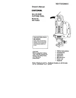
Page 51: ... 02AS 000276 00 Tornillo de la base 6 02AS 000258 00 Tornillo industrial 2 02AS 000258 10 Tornillo industrial 2 02AS 000260 00 Tornillo industrial 1 02AS 000290 00 Tornillo 1 02AS 000291 00 Tornillo 1 02AS 000292 00 Tornillo 1 02AW 000068 00 Arandela ondulada 1 02AW O00070 00 Aros extemos de sujecibn 2 2213 MA0001 00 Barra de guia 2 2213 MA0003 00 Cabezal 2 2213 MA0004 00 Guia indicadora 1 2213 MA...

Page 52: ... de recambio accesoriosy manuales del propietario que requiera para hacerlo usted mismo Ilarnea Sears Parts Direct s 1 800 366 PART De 6 a 23 horas HEC 7 d as a la semana 1 800 366 7278 sblo en EE UU www sears comlpartsdirect Para adquirir o pedir informacibn sobre un Contrato de servicio de Sears o un Contrato de mantenimiento de Sears 1 800 827 6655 EE UU 1 800 361 6665 Canada Regtstered Tradema...

Reviews: