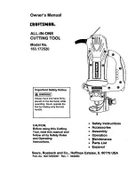
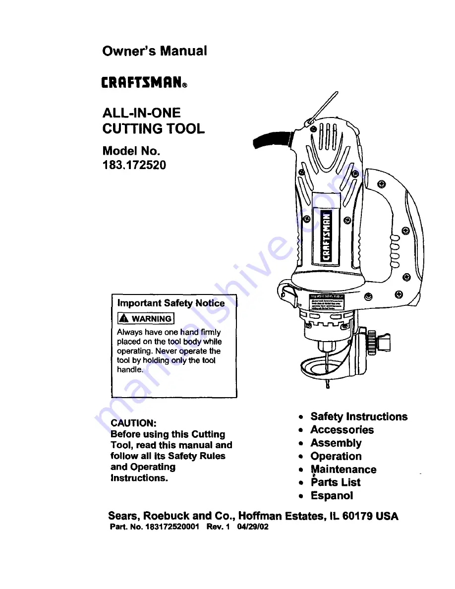
background image

Summary of Contents for 183.172520

Page 1: ...y while operating Never operate the tool by holding only the tool handle CAUTION Before using this Cutting Tool read this manual and follow all its Safety Rules and Operating Instructions Safety Instructions Accessories Assembly Operation _aintenance Parts List Espanol Seam Roebuck and Co Hoffman Estates IL 60179 USA Part No 183172520001 Rev 1 04 29102 ...

Page 2: ...ome examples of these chemicals ere Lead from lead based paints Crystalline silica from bricks cement and other masonry products Arsenic and chromium from chemically treated lumber Your risk from these exposures vadsa depending on how often you do this type of work To reduce your exposur_ to these chemicals work in a well ventilated area and work with approved safety equipment such as these dust m...

Page 3: ...ng and changing accessories 20 CHECK FOR DAMAGED PARTS Before further use of the tool a guard or other part that is damaged should be carefully checked to ensure it wdl operate properly and perform its intended function Check for alignment of mowng paris binding of moving parts mounting and any other condihons that may affect its safe operation A guard or other part that Is damaged should be prope...

Page 4: ...IT STEADY WHEN CUTTING Thts wnllfree both hands for oberatnngthe tool 11 NEVER HOLD THE WORKPIECE IN ONE HAND whale operating the tool wnth the other hand 12 NEVER PLACE HANDS iN THE PATH OF THE CUTTER AND UNDER THE WORKPIECE 13 NEVER START THE TOOL WHEN THE BIT IS TOUCHING THE WORKPIECE The butmay catch the workpaece causing loss of control 14 ALWAYS HOLD THE TOOL WITH TWO HANDS DURING START UP A...

Page 5: ...ke sure your extension cord is in good condition When using an extenslon cord be sure to use one heavy enough to can_ the current the tool will draw An undersized cord will cause a drop m llne voltage resulbng nloss of power and overheahng The table below shows the correct s_ e to usa eccordmg to cord length and nameplate ampere rating If m doubt use the next heawer gauge The smaller the gauge num...

Page 6: ...te Carefully unpack the cuttmg too and all its components Compare against the Cutting Tool Components chart below NOTE See Page 7 for illustration of components I_ WARNING I To avoid fire or toxic reaction never use gasoline naphtha acetone lacquer thinner or similar highly volatile solvents to clean the cutting tool CUTTING TOOL COMPONENTS KEY I DESCRIPTION QTY Inside Carrying Case A Cutting Tool...

Page 7: ... f f_ E H D F c 7 ...

Page 8: ...hng Knob Locking Knob C1r_ Cuthn Motor HOUSIng Qu_k Lever Mounhng Insed Mounta_ Bracket D_sc Motor Housqng Pma_on Handle Motor Hous ng _ Depth Scale Depth Rod He hi Knobs Qumk Lockm Lever Plate Lockm Knob Router Base plunge Ac_on Turret Bevel Adlushng Lock ...

Page 9: ...onIN use the colletwrench 3 to turn the collet nutcounter clockwise Loosenthe collet nuttwo or three turns 3 Removebit if one is already installedinthe tool Insert new cutting bit 4 into the collet IA WARNING I Insert the bit all the way into the collet and then pull it back between 111e and 1Is This creates an air space between the motor shaft and the bit to help prevent overheating the bit Befor...

Page 10: ... the bottom of motor housing 2 untilthe slot in the bracket 3 lines up with the shaft locking button 4 in the motor housing NOTE The mounting bracket must be pushed onto the motor housing as far as it wdl go Lock the sole plate to the motor housing by snapping the quick locking lever 5 firmly against the motor housing 2 4 3 5 Fig 4 ADJUSTING FREEHAND SOLE PLATE Adjust freehand sole plate depth by ...

Page 11: ...ll cause the tool to twlsL L Fig 6 PRACTICE CUTS USING FREEHAND SOLE PLATE 6 Set the speed control switch to the appropriate speed 7 Turn the swntch ON When the motornsupto fullspeed slowiyttp the tool to an upnghtposttnon lettnng the bitcut nntothe workpnece see F g 7 Once the toolhas reached the uprightpesubonand the bithas cutthroughthe workplece slowlymove the tool in a clockwise dnrection usn...

Page 12: ... install freehand sole plate as outlined on Pages 9 10 of this Owner s Manual AdJustdepth of cut so the bit wdl protrude _ 8 beyond the thickness of the drywall Hold the tool firmly with both hands and turn it ON Plunge the bd through the drywall at the mark mdlcahng the center of the box See Fig 8 for cutting pattern Fig 8 CUTTING OUTLET OPENINGS IN DRYWALL cont d 6 Move the bit slowly to the ngh...

Page 13: ...ate 9 in or out as required see Fig 11 NOTE Set the depth gauge so the cuttmg bit protrudes beyond the sole plate 1 8 more than the thtckness of the matenal being cut For example d you are cutting 3 4 pine the bit should protrude e beyond the sole plate 2 Securely tighten depth gauge knob 3 Beforestartingto cut you shouldre checkbitdepth make suresole plate is at rightangles to the bit and securel...

Page 14: ...on the workptece with the btt at an angle of about 450 see Fog 13 Insert the circle cutter pivot point into the pilot hole dnlled at the center of the ctrcle NOTE DO NOT let the b_tcontact the workptece before swttch ts turned ON and the tool is up to full speed CIRCLE CUTTER OPERATION cont d 5 Turn the switch ON When the motor is up to full speed slowly hp the t_ and clrole cutter assembly to an ...

Page 15: ...router base up and down on the gutde rods and locking dun place Rause plunge router depth stop rod by turning the lower depth stop lock nut 1 counter clockwise untul t is posutnonedat the bottom of the depth stop rod 2 see Fig 16 Push depth stop quick release button 3 and reuse the depth stop rod to Its maximum height and then release the button 2 Rotate plunge actuonturret 4 untilthe shortest sto...

Page 16: ... enough to allow router to freely sltde up and down on the guide rods 11 Two add t onaldepths can be pre set na s milarway setting the other two turret stop screws to the desired depth NOTE To select pre set plunge depth simply rotate the turret until the correct turret stop screw is aligned under the depth stop rod SETTING ROUTER BASE BEVEL Bevel cutting with the cutting bit can be done with the ...

Page 17: ...t collet see Fig 3 2 Install router bit and securely tighten 3 Adjust router base height to the con ect routing depth 4 Turn the swutch ON making surethe routerbut is not touchinganything 5 Holding the tool by the two height adjusting knobs carefully lower the bit onto the workplece and guide the bit around the desired pattern CU I rlNG STRAIGHT LINE WITH STRAIGHT EDGE To cut a straightline youcan...

Page 18: ...en cleaning plastic parts Most plastics are susceptible to damage from various types of commercial solvents and may be damaged by their use Usa clean cloth to remove dirt dust oil grease etc Do not at any time allow brake fluids gasoline petroleum based products penetrating oils etc to come in contact with plastic parts They contain chemicals that can damage weaken or destroy plastic INTERNAL CLEA...

Page 19: ...Main Unit 19 ...

Page 20: ... Tnac 34 03AM 000104 00 Stator 35 03AM 000105 00 Rotor 36 03AP 000073 00 i PCB 36 03AP 000073 10 PCB 37 03AP 000076 00 PCB 37 03AP 000076 10 PCB 38 03AR 000013 AO Resistor 39 03AR 000015 D0 Resistor 40 03AR 000109 A0 R_ _i_tnr Qty Key Part 1 41 03AS 000135 00 1 42 03AS 000140 00 2 44 03AT 000033 00 2 48 03AT 000040 00 1 49 03AT 000046 00 1 50 03AW 000131 00 4 50 or03AW 000131 10 2 53 03AY 000020 0...

Page 21: ...08 2213 MA0010 00 211 2213 PA0010 00 212 2213 PA0011 00 213 2213 PA0012 00 214 2213 PA0013 00 215 2213 PA0014 00 216 2213 PA0015 00 Part Name F xlngshaft Releaselock pin Screw Freecutmetal round guide Lock Fixbase Piast c guide base AdjustmentGear 15T Sleeve Sclew lockF Qty 1 1 1 1 1 1 1 1 1 1 21 ...

Page 22: ...014 00 326 2213 PA0015 00 327 2213 PA0016 00 328 2213 PA0017 00 329 2213 PA0018 00 330 2213 PA0019 00 331 2213 PA0020 00 332 2213 PA0021 00 Part Name Qty Fixingshaft 1 Releaselockpin 1 Compressivespnng 1 Screw 2 Screw 1 Screw 3 Washer 1 S roundguide holder 1 Lock 1 Plasbcguidebase 1 AdjustmentGear 15T 1 Sleeve 1 Screw lockF 1 Anx righthandle 1 Anx left handle 1 Anx handlesoftgrip outs de 1 Anx han...

Page 23: ... 00 412 2206 MA0003 00 415 2206 PA0001 00 416 2206 PA0003 00 417 2206 PA0004 00 418 2213 PA0007 00 419 2213 PA0008 00 Part Name Qty I Square nut 1 Hexagon thin nut 1 Machine screw 1 Screw 1 Spdng washer 1 Cimular arm metric 1 Cimular arm inch 1 Washer 1 Handle bush 1 Dgstance lock w thcenter pin 1 Locking base 1 Round guide mount 1 Handle cuplike base 1 Handle cuplike cover 1 23 ...

Page 24: ...Router Assembly 24 ...

Page 25: ... PA0001 00 152 2213 PA0002 00 153 2213 PA0003 00 154 2213 PA0004 00 155 2213 PA0005 00 156 2213 PA0006 00 157 2213 PA0007 00 158 2213 PA0008 00 159 2213 PA0009 00 164 2205 PA0004 00 165 2205 PA0007 00 Part Name Fixingshaft Base release lockpin Heightrod Guide bush Routertile base Spring Spring Spring Screw nut Square nut M4 fixing nut Steel ball Screw Machinescrew Base screw Machinescrew Screw Scr...

Page 26: ...ll Sears PartsDirectSM 1 800 366 PART 6 a m 11 p rn CST 7 days a week 1 800 366 7278 U S A only _ www sears comlpartsdirect To purchase or inquire about a Sears Service Agreement or Sears Maintenance Agreement 1 800 827 6655 us A 1 800 361 6665 Canada 7 a m 5 p m CST Mon Sat 9am 8p m EST M F 4 p m Sat Para ped rserwciode reparacibna domzcilio y para ordenarpiP_s 1 888 SU HOGAR sM 1 888 784 6427 Au...

Reviews: