background image

Summary of Contents for 161.210400

Page 1: ...les For Safe Operation and Complete Operating Test Procedures Carefully PRINTED iN U S A _ CRRFTSHRN ENGINE ANALYZER FOR 12 24 VOLT SYSTEMS OPERATING INSTRUCTIONS SAFETY RULES TUNE UP PROCEDURES REPAIR PARTS I I I II Illl 11 IIIIIII IIII 11 SEARS ROEBUCK AND CO U S A CHICAGO ILLINOIS 6068 4 2 17070_ ...

Page 2: ..._X ST llli_l _ST liilli_l TEst m ilIl TEST _U_ER tEPt ACfi I_ R ILAc MENI 34 Lo_ v_XAG OnOP T STS ST _I_ E SStOII COtI_O 1_ TIE los S2 HF _ illIIlllNGS t8 lii l Ai Wlli lOi lffN OtTil IIlD _4B ELEC NICAL iIRIN_ltARNE S _9 e _T_ LIST t ...

Page 3: ...ng Oak Brook Illinois 6052 National Service Data Book National Automotive Service Inc Div Glenn Mitchell Manuals Inc Box 10465 San Diego Ca ifornia 92110 Chilton_s Auto Repair Manual Chllton Company 56th and Chestnut Streets Philadelphia Pennsylvania 19139 GM Diagnosis and Repair Manual GM DR Manual Headquarters P O Box 1185 Southfield Michigan 48075 Chrysler Corporation Service Publications Dept ...

Page 4: ...0 seek medical a_d The gasesgenerated by a chargtng bat tory are highly explosive Do not smoke or permit flame or spark to occur near o battery at any tlme particular ly when it Is charglng Any room or v 9_ 10 II i2 13 14 15 comportment ontaining charging bat terles should be well ventilated to prevent accumulaHon of explosive gases To avoid spark_ do ru_tdisturb the battery charger connectlonswhi...

Page 5: ...T Insert RED plug on Amps lead WHITE OHMS SOCKET Insert WHITE plug on Ohms lead BLUE RPM PICK UP SOCKET Insert Blue plug on inductive pickup lead 6 BLACK OTHER TESTS SOCKET In sert BLACK plug on test lead OTHER TESTS SELECTOR SWITCH Always place switch In CENTER posi tion for all tests indlcoted by functlon switch No B above Use left hand posl tlon for charging Amps and right hand positton for sta...

Page 6: ...tests 5 DWELL Used to check point dwell on breaker polnt ignitton systems Read 45 scale fo 8 cvi o 60 scale for 6 cyl and 90 scale for 4 cyt engines ALTERNATOR Indlcates alternator condition on GOOD or DEFECTIVE sca te wlth englne running It w ll detect open or shorted diodes or windings OHMS HI Lo used to measure electrical resistance in Ohms on ignition cables ballast resistOrSeor ignition coil ...

Page 7: ...le tests G M DIAGNOSTIC CONNECTOR ADAPTER Used to make tests on G M cars equipped with the diag nostic connector PRIMA RY COIL ADAPTER Used to provide easy hook up on ignLtion sys tems with insulated call primary con necHons 9_ H E i ADPTER Used to provide Dwell connection on G M H E I systems _ _ Itrtrnlnrlrllllllrlrlll TEST LEADS FIGURE 4 The plugs and socketsare pol arized to insure correct att...

Page 8: ...ermlnai on call primary Attach RPM induction pickup to a spark plug cable as close to dlstrtbu tar cap as possible Jaws must be fuliy closed DO NOT cc_nect OHMS clip I Engine must be at operating tempera ture before testing Proceed with tests as outt_ed in this manual Starter Amp shunt must remain closed at all times except for charging sys tem test as indicated Damage to Battery Adaptor can occur...

Page 9: ...Engine must be at operating temperature before testing Always close starter shunt b6fore starting engine SEE PAGE No 6 FOR NUMBER IDENT IFICATION _PLUG WIRE TO BE JAWS MUST CLOSE SO UPPERAND LOWER POLE PIECES TOUCH EACH OTHER i BLUE RED _LACK CLAMP TACH PICK UP MUST BE CLOSE TO DISTRIBUTOR CAP AS POSSIBLE IEEN CLOSE STARTE_ SHUNT FOR STARTER AMPS OPEN FOR CHARGING AMPS _ __ See Test Numbe r 1 5for...

Page 10: ...ge battery to full charge condition 6 Excessive fluctuating voltage reading over i volt can be caused by a starter in poor condition due to worn bearings dirty commutator a defective battery or corroded starter cables Clean tight connec tions are a must throughout the starter system BA TTERY V OLTS BLACK CLIP RED CLIP STARTING AND CRANKING VOLTAGE TEST CONNECTIONS FIGURE B L SOLENOID TERMINAL S GR...

Page 11: ...unction switch in POINTS position and read 3 volt points scale Each division is I volt 3 Disable engine to prevent starting by grounding HV iead of the coil as shown below On HEI or electronic systems disconnect battery lead at coil or unplug distributor pickup coil connector 4 Refer to starter system illustrated below Connect GREEN and BLACK clips across each section of circuit shown by numbers i...

Page 12: ... Read test results on the appropriate VOL_S scale 3 Be sure the shunts are in position on the Battery Amps Adapter as shown in Key No I Page 5 before starting the vehicle CAUTION TIGHTEN ALL NUTS ON THE BATTERY ADAPTOR FIRMLY WITH A WRENCH TO AVOID EXCESSIVE HEAT AND POSSIBLE SHUNT DAMAGE 4 Before performing Step 5 start the engine and allow it to run for 10 to 15 minutes or until the engine compa...

Page 13: ...he alternator position turn lights on and operate the engine at approximately 1200 RPM Read the aiternator scale A reading in the gray defective zone indicates defective diodes or windings in which case the alternator diodes and windings are functloningproperly Figure 12 10 If a low or no charging rate is indlcated check alternator output under full field conditions by removing voltage regulator c...

Page 14: ...l Horizonhal Jumper Connect Jumper CHRYSLER to ground FIGURE i7 A Field Terminal Vertical Blue Wire JJL _ Remove cap from the field Stator terminal Connect jumper Terminal wlre to field terminal and ground Ground Terminal FIGURE 17 C Field Term hal Regulat_ Terminal IIATTERY _ft AOAPTI R CONN tCtlONS ItOlt ALTERNATOR Tilt FIGURE 14 FIGURE 16 A CIRCUIT Electronic Voltage Regulator Insert screwdrive...

Page 15: ... 1111111111111111111111111111111111 On some vehicles if may be inc_onvenlent to connect the iumper wlre at the alternator Im such a iftuaHon remove the regulator con nector from the voltage regulator and onnect a iumper wire as illustrated ignition Remove field lead from field terminal Connect iumper w_re from positive terminal of battery to the field lead Battery Ignition Switch Jumper Batter Reg...

Page 16: ...ype B system is on the vehicle Also check the rated output of alternator on the nameplate or specifications listing 1 To perform this test it is necessary to ground the field in the type A Circuit or remove the regulator from the charging system and energize the field in the Type B Circuit This provides full field operation and the alternator will charge at its maximum rated capacity 2 Place the F...

Page 17: ...e disconnect jumper lead remove the shunt and reconnect wiring harness plug connector or field wire to the regulator for normal operation Repeat Test Number 4 Charging System Vp tage and Current If the voltage reading is within the range as specified by the vehicle service manual typically between i3 8 and 15 2 volts on 12 volt systems and 27 6 and 30 4 on 24 volt systems the regulator is satisfac...

Page 18: ... the component to be tested and read the prope_ Ohms scale X 1 or x 1ooo 4 IMPORTANT CAUTION ALWAYS disconnect ALL L ADS from any electrical part to be tested on the vehicle Failure to observe this caution may result in damage to the tester 5 Refer to manufacturer s specifications for normalresistance value of any part being tested ignition cables ballast resistor coil windings etc WHITE PLUG FIGU...

Page 19: ...tator leads disconnected as illustrated To facilitate checking the diodes in the end frame and heat sink place a short length of wire or nail in the jaws of the RED and BLACK test clips as shown in the illustration Touch the RED lead to the diode case and the BLACK lead to the diode lead as illustrated in Step A and note the meter reading Reverse the lead connections on the same diode and again no...

Page 20: ...lternator should be repaired or replaced To check for grounds connect the tester leads to each stator lea_ and to the frame If the meter shows a full scale reading the stator is not grounded if the meter is near zero left end the stator winding is grounded to the frame and the alternator should be repaired or replaced The purpose of this test is to confirm the presence of supply voltage to the pos...

Page 21: ...olts with the points closed a problem exists in one or more of the following areas Ignition coll primary open Pigtail from negative or Distributor Dist side of co11 to distributor open points defective or open ground within the Distributor If the Voltmeter stays at zero no reading a problem exists in the supply circuit to the ignltion Coil i e ballast resistor open when equipped ignition switch or...

Page 22: ...GOOD condition if the reading is 3 volts or less Replace points if the reading is out of the good zone or over 3 volts 5 If the reading still exceeds 3 volts check the distributor ground plate plate on which points are mounted pigtail extension to primary lead inside distributor or primary lead to coil for breaks or misaligned point contacts on points Refer to your vehicle service manual for other...

Page 23: ...nder scale to correspond to the engine under test 4 Compare results to vehicle specifications_ adjust _o correct dwell if required READ PROPERSCALE TO SUIT NUMBER OF ENGINE CYLINDERS BLACK RED J CLIP CLIP _J BAT COIL _ FIGURE 22 DWELL ADJUSTMENT CONNECTIONS GREEN CLIP DIST DISTRIBUTOR On engines that have a sliding window in the distributor cap adjust dwell as follows I Operate engine at specified...

Page 24: ...remote starter switch to the vehicle or have an assistant crank the engine for you with the ignition switch 4 Turn the ignition switch on and with the engine_cranking observe the reading on the dwell scale 5 To adjust dwell loosen LOCKING screw slightly and adjust point gap by turning ADJUSTMENT screw Figure 25 or by inserting a screwdriver in slotted hole Figure 26 and turning the tool slightly l...

Page 25: ...NG WHEVEVER THE DWELL ANGLE HAS BEEN ADJUSTED When the dwell angle is increased the timing is retarded Conversely when the dwell angle is decreased the timing is advanced In fact there is a one to one ratio between dwell and timing For every one degree change in dwell there is a corresponding one degree change in timing This can sometimes be used to make minor changes in timing If for example it i...

Page 26: ...nge in reading increase engine speed to approximately 1500 RPM and then return to idle 4 Reconnect vacuum advance hose s 8 15 2O 25 3O I0 35 5 40 0 45 FIGURE 28 DWELL VARIATION Variation on 4 6 and 8 cylinder engines should not exceed 3 degrees if it does check for a wear in distributor shaft b wear in distributor shaft bushing c wear in breaker plate NOTE Manufacturer s specifications for some en...

Page 27: ...rument as outlined under Description Zero Adjuster above Attach the test leads to the instrument and proceed to the section in this manual describing CONNECTIONS FOR TESTING the appropriate vehicle CONNECTIONS FOR TESTING Ford On Ford cars with 1974 electronic ignition systems use the Ford adapter pin as shown in Figure29 below Connect the GREEN clip from the Craftsman Engine Analyzer to the adapt...

Page 28: ...n Figure31 below Connect the GREEN clip from the Craftsman Engine Analyzer to the spade teHminal adapter Just installed Connect the RED cllp to the posltive battery terminal and the BLACK cllp to a clean and secure ground such as the engine block NOTE Experience has shown that this is the easiest way to make a dwell connection to GM vehicles Only if your vehicle does not have an ENGINE ELECTRICAL ...

Page 29: ...ock CONNECT GREEN CLIP TO THIS TERMINAL DWELL CONNECTION TO GENERAL MOTORS CARS WITH SEPAPJ_TE IGNITION COIL FIGURE 32 On the General Motors integral ignition coil V 8 and V 6 HEI systems slide the adapter onto the TACH terminal as shown in Flgure 33 below Connect the GREEN clip from the Craftsman Engine Analyzer to the adapter just installed Connect the RED cllp to the positive battery termlnal a...

Page 30: ...LL reading obtained should meet the manufacturer s specification for that engine If it does not consult the manufacturer s shop manuals for diagnostic procedures General Motors I Connect the test leads from the Craftsman Engine Analyzer as shown in Figure 31_32 or33 as appropriate to the vehicle under test Keep the leads clear of fan belts and pulleys 2 Continue with steps g through 5 as described...

Page 31: ...te the position of the fly wheel mark in relation to the degree indicator Compare to specified initial timing If not within specifications readjust distributor as required 7 TIMING ADJUSTMENT To change timing loosen the d_stributor hold down screw or bolt and rotate the distributor body as shown in Figures 36 and 37 until proper timing is indicated Test Number 17 TimingAdyanceSystems NOTE The foll...

Page 32: ...rr i rrrlll ROTATION II 1 Ii_ _ _ FIGURE 35 11111111 hill I IH I1 ifll i lllll Rotor Rotor Rotation Rotation Advance Retard Advance FIGURE 36 FIGURE 37 Hold down screw or bolt ROTATION Vehicle Battery Tester PlckuI SEEPAGES 6 AND 7 FOR PROPER HOOK UP FOR RPM NO I SPARK PLUG FIGURE 38 ...

Page 33: ...complex advance systems IMPORTANT DO NOT ATTEMPT TO SERVICE THESE ELECTRONIC ENGINE SYSTEMS WITHOUT THE VEHICLE SERIVCE MANUAL Some of the Systems currently in use are Chrysler Corporation ELB Electronic Lean Burn introduced in 1976 Re named ESA Electronic Spark Advance in 1979 Ford Motor Company General Motors EEC I EEC II EEC 111 Electronic Engine Control introduced in 1977 ESS Electronic Spark ...

Page 34: ...s obtained When making any mixture adjustment only turn the mixture screw i 8 of a turn at a time Between adjustments allow about 30 seconds for the engine speed to stabilize Figuro 40 4 MULTI BARREL CARBURETORS Repeat procedure described in Test Number 3 on EACH mixture screw until the smoothest maximum RPM is obtained Turn each screw i 8 of a turn at a time to prevent engine stalling If the fina...

Page 35: ...n the run position voltage is applied to the solenoid energizing it and causing it to move the idle position of the throttle Curb Idle is adjusted with the solenoid energized When the key is turned off the solenoid retracts and allows the throttle plates to close or return to a base idle hence sh_tting off the fuelialr supply to the engine By using the RPM VOLTS and OHMMETER sections of your Craft...

Page 36: ...st idle cam releases the fast idle adjustment screw completely Engine Idle speed is then controlled by the curb idle adjustment screw Fast idle adjustment procedures differ among the various automobiles Consult your specific vehicle service manual for proper procedures It may be necessary to bypass one or more spark timing or emissions system controls either vacuum or electric while adjusting the ...

Page 37: ... terminals as illustrated in Figure 42 4 Observe reading on the Low Ohms scale then re connect primary wires BLACK Ao B4 FIGURE 42 PRIMARY RESISTANCE TEST CONNECTIONS The reading should meet the vehicle manufacturer s specifications Generally the coil primary winding resistance should be between I and 2 ohms Check your vehicle service manual for the exact value if the reading is substantially abov...

Page 38: ... plug adapter and insert in the coil tower as shown 3 Read the Ohms X 1000 scale on the meter and compare the reading with the manufacturer s specification in the next column TEST RESULTS The resistance of most coils for standard ignition systems are given in the table below _NUFACTUREB SECONDARYRES STA_4CE_ OHM_S American Motors 6 500 to 9 500 Chrysler g Bo0 to 11 500 Ford 7 500 to 9 000 G M Delc...

Page 39: ...its overall performance will deteriorate I Remove the cables from the engine When removing the wire from the spark plug grasp the spark plug boot and twist and pull wire with a firm steady force DO NOT yank on the cable to remove it 2 Use the X 1000 position on the RANGE SELECTOR of the Craftsman Analyzer 3 Connect the RED and BLACK Ohn netertest leads to the ends of the cable as shown below and u...

Page 40: ...to test the ballast resistor To test the ballast resistor disconnect all leads at their terminals to pr vent possible damage to the analyzer or to prevent inadverdent measurement of other circuits connected to it CONNECTIONS Ii 2 Insert the white plug OHMS lead into the corresponding tester socket Connect the RED and BLACK clips to the ballast resistor as shown Some ballast resistors are dual unit...

Page 41: ... of your vehicle service manual your Craftsman Voltmeter and or Ohmmeter can confirm operation of the ignition switch Some of the ignition switch functions are as follows i Activate starter relay start position 2 Bypass ignition ballast resistor start position 3 Confirm tell tale cluster lights start position 4 Activate ignition 5 Activate accessories If you have difficulty with any of the above c...

Page 42: ...analyzer It would be advlseable before beginning these tests to review the use of the VOLTS OHMS and POINTS positions of your analyzer as shown earlier in this manual American Motors 1975 76 American Motors 1977 Up See Ford Motor Co Chrysler Corporation Ford Motor Company General Motors integral Coil General Motors External Coil Test Number 27 Amerlcan Motors Electronic igni_tl pn _ Sys tem Te st_...

Page 43: ...dule can result _r _ _ _ _ _ _ PRIMARY SYSTEMS WITH SEPARATE COIL Remove high tension coll wire from colt secondary terminal Connect Jumper Wire between coil secondary terminal and a good ground on the engine LI _ IL IILILI _II LJLI l _I I IILIIIIIILIi HEI WITH ELECTRICAL DIAGNOSTIC CONNECTOR Insert the GM Diagnostic Connector Terminal in terminal No 6 of Electrical Diagnostic Connector Connect ju...

Page 44: ...NAL HIGH TENSION ITPUT TERMINAL ELECTRONIC MODt LE IGNITION SWITCH COIL COIL TERMINAL GROUND BLACK NEG4 POS 12 VOLT BATTERY DISTRIBUTOR CONNECTOR GROUND DISTRIBUTOR DISTRIBUTOR SENSOR UNIT FIGURE 46 AMERICAN MOTORS ELECTRONIC IGNITION SYSTEM ...

Page 45: ... connector With Ignition Switch on meter should read between 5 o_d 8 volts If OK proceed tO Test F if less thor_ 5 Volt or more than 8 vohst pro ceed wt_ elf O WIth distributor connector unplugged and call negotlve lead dIsconnected meter should read between 7and 2 5 _mswith Ign t o_ Switch ofF if not _eploce o t 5 With ign_Hon Switch off and negative call lead dis Coil hlgh connected connect RED ...

Page 46: ...S IGNITION SWITCH I2 V BATTERY GROUND COMP RESISTOR SIDE NOTE LOCATION H DUAL BALL _ST AUXI LIARY RESISTOR SIDE ELECTRONIC CONTROL UNIT COIL FIGURE 47 ISTRIB CONNECTOR DISTRIBUTOR CHRYSLER ELECTRONIC IGNITION SYSTEM ...

Page 47: ...nect Cull BLACK e ltp to t_er contact With Igmition off meter To_er sl_JId read 5 000 to 25_000 ohms l it does not re Contact place coil io mov oth s p on ram Bo os o w th psl Ballast cot_t_ected to Terminoh 9 and t0 on Ba last_ meter _hauld Termlno I C_p Side read 0 2 t_ 1 5 ohms if it does _Ot replace Ba lc_st O Balt_t OHMS 4 3 Remove both Slip on Termir_t_ from Ballast a d with Rei stanCe X 1 B...

Page 48: ...YELLOW IGNITION SWITCH 12 V BATTERY GROUND D E C MODULE TO BAT TERMINAL DISTRIBUTOR GROUND BLADES FIGURE 48 SOCKETS ORA I BLACK LE BLACK ORANGE BLUE _OWN FORD ELECTRONIC IGNITION SYSTEM inspect Harne_s Connectors for white blue leod terminal as 1974_ 1975 and later models ...

Page 49: ...e wire With ignitior_ Switch off meter should iead i to 3 ohms If it does not replace ignttiot_ Coil 1f OK proceed with Test D Remove call high tension lead From coil rowe C0nne_t BLACK llp to inner omact With _g_itfo_ Switch off mete_ should read 5 000 tO 25_000 ohms I it does not replace coil With Ignitlot_ Switch or_ meter should read 5 to volts if higher thot_ 7 votts_ recheck Test B If Iowe p...

Page 50: ...SION OUTPUT CONDENSER IS USED ONLY FOR RADIO INTERFERENCE SUPRESSION AND NOT AT ALL INVOLVED IN IGNITIOI PERFORMANCE BROWN GROUND LOWER HOUSING HARNESS DISTRIBUTOR WiTH CAP AND ROTOR REMOVED WHITE PiCK UP EN LEADS ELECTRONIC MODULE DELCO HEI IGNITION SYSTEM WITH COIL IN DISTRIBUTOR CAP FIGURE 49 ...

Page 51: ...ect PI_ Le_d 4 lie s_xe st mrthree hod Lower Dl_t Cap Battery Houd_g Horm_l tt dh_onnected _rom Olsttlbutor Cap _ Term Nag tarmacs REDclip to C _ term _l With Ignltlm Switch on meter shouldread at loess IO veiN S 1 With REDclip connected to B Termir_l end ignition B Swltch on meter shou_ldreed at leatt 10 volts If lower Term at Battery or ere recheck Test_ If till low e_amlne termlnoh Dlst Cop Nee...

Page 52: ...CH FEED TERMINAL POS COiL CONNECTOR NEG HIGH TENSION OUTPUT TERMINAL L HOUSING HARNESS GROUND FIGURE 50 CONDENSER iS USED ONLY FOR RADIO INTERFERENCE SUPRESSiON AND NOT AT ALL INVOD ED IN IGNITION PERFORMANCE DELCO HEI IGNITION SYSTEM WiTH SEPARATE COIL ...

Page 53: ...tween 6 000 Output Term rot a_d 12 000 ohms If not replace ot Reconnect Terminal High TensIon Wire tri_ l l Remove disl_ Ibuto cap and rotor Reconnect Colt Con Lowe_ Ha_ing Harness Red 16 VOLTS Term nall_ Battery necta and Ignition Feed Wire to Coil With Ign tion Continuity on Neg Swffch on_ meter should re_d at ieatt 0 volts tf lower repair at replace i_wer Housing Ha_e Module F Lower Housing H a...

Page 54: ...vice manual f_r your vehicle and engine combination CONNECTIONS On G M cars equipped with the C 4 System a small green single contact DWELLMETER connector is normally provided to check the DWELL voltage to the carburetor usually located under the hood near the right front fender wheel well or near the carburetor protruding from the wiring harness DO NOT ALLOW THE LEADS TO TOUCH GROUND OR HOSES THE...

Page 55: ...r mounted on the exhaust manifold working through the ECM This sensor must typically be above 6000 F to operate properly Engine cooling restart or excessive idling could cause the sensor to go below 600 F in which case the DWELLMETER reading will be some FIXED value between I0 and 50 This syst m may require three to four minutes to reach temperature after a restart or cool down to resume the VARYI...

Page 56: ...or Switch to the POINTS LO VOLTS position 4 Start engine and operate at approximately 1200 RPM B Turn on headlights and note reading on the 0 3 2 Volt scale GOOD A reading less than i volt indicates a good ground strap and connections HIGH A reading exceeding I volt indicates a defective ground strap or its connections Clean the ground strap connections and repeat test before replacing ground stra...

Page 57: ...ry associated with the fuse that is to be tested Then touch both sides of the fuse with the RED clip If the meter indicates battery voltage on both sides of the fuse the fuse is good If it indicates battery voltage on one side and nothing on the other the fuse is open If there is no reading on either side there is an open circuit between the fuse and the battery RED _REEN CLiP NOT On General Motor...

Page 58: ...verse leads for a positive ground system HORN AND RELAY CIRCUIT CONNECTIONS TEST RESULTS FIGURE 54 ZERO READING I Defective horn relay 2 Defective horn rlng 3 A break in wtr ng be tween the horn ring and relay MORN BLACK 6 10 r READING LESS THAN i0 VOLTS 1 Defective horn 2 Defective wires 3 Relay points not making good contact HORN RELAY GOOD Horn oper ating range BATTERY VOLTAGE READING 1 Open ci...

Page 59: ... not used Corroded or loose connections and frayed or broken cables can cause excessive voltage drops in the starting circuit which can cause hard startlng To test for these conditions connect the clips between I and 2 2 and 3 4 and 5 5 and 6 6 and 7 7 and B with the starter turning Be sure the high voltage lead is disconnected from the coll so the engine won t start During this test no reading sh...

Page 60: ...the white plug OHMS lead into the corresponding tester socket Connect the RED and BLACK clips to the lamp under test Some lamps have two filaments and each must be tested separately 3 Set the Function Selector switch to the OHMS position 4 Set the Range Selector Switch to the LOW scale The cold filament resistance will read very low typically less than 10 OHMS 5 If the meter reads oo extreme right...

Page 61: ...ing voltage in this system approaches 120 Volts A C Do not attempt to test this system while llve Make only Ohmeter Tests as instructed in the Ford Manual with the engine offl Test Number 34H Electrical Wiring Harness All power distribution within the vehicle takes place _ia one or more color coded wiring harnesses If a wire in the harness breaks or a connector is loose or corroded voltage will no...

Page 62: ...I lulul C_i _ i Ji ...
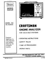
Page 63: ...r Tests 13 38 568 Cable Auemblyw toch Pick Up 14 38 514 Cable Assembly Amp Cable Only 15 1000 840 Battery Adaptor 16 1000 2 52 Shunt and Terminal Assembly 17 180 457 Starter Shunt 18 260 183 Thumb Screw 19 260 171 Screw Flex 3 8 i6 x 1 1 4 Lg 20 180 618 Battery Adaptoru Male 2 i 1000 248 A Iternatar Adaptor 22 180 298 Adaptor Spdng Foreign 23 180 293 Adaptor Sprlng Domestlc 24 38 396 Wire Adaptor ...

Page 64: ...mber of your ENGINE ANALYZER can be found on the front of the instrument WHEN ORDERING REPAIR PARTS ALWAYS GIVE THE FOLLOWING INFORMATION l PART NUMBER PART DESCRIPTION MODEL NUMBER NAME OF ITEM All parts listed may be ordered from any Sears Service Center and most Sears stores tf the parts you need are not stocked locally your order will be electronically transmitted to a Sears Repair Parts Distr...

Reviews: