background image

Summary of Contents for 152.213361

Page 1: ... No 152 213361 C CAUTION FOR YOUR OWN SAFETY Read and follow all of the Safety and Operating instructions before Operating this Dust Collector Customer Helpline 1 800 897 7709 Please have your Model No and Sedal No available Sears Roebuck and Co Hoffman Estates JL 0179 U S A Part No OR92136 Revision A Espa5olpg 21 ...

Page 2: ...s which vary from state to state Sears Roebuck and Co Dept 817 WA Hoffman Estates IL 60179 induction Motor Continuous duty HP Maximum developed HP Amps Volts Hertz RPM Filter Bag Top Collection Bag Bottom Collection Hose Maximum C RM Maximum static pressure in inches of water Filter Bag capacity Collection Bag capacity 1 2 10 8 120 6O 3450 R R M no load R P M 30 micron 30 micron 4 inch Flexible Ho...

Page 3: ...ly when the electrical tool is operating 7 DO NOT FORCE THE TOOL to perform an opera tion for which it was not designed it wiii do a safer and higher quality job by only performing operations for which the tool was intended 8 WEAR PROPER CLOTHING DO NOT wear loose clothing gloves neckties or jewelry These items can get caught in the machine during operations and pull the operator into the moving p...

Page 4: ...h Avoid breating the dust and avoid prolonged contact with dust Allowing dust to get into your mouth or eyes or lay on your skin may promote absorption of harmful material Always use properly fitting NIOSH OSHA approved respiratory protection appropriate for the dust exposure and wash exposed areas with soap and water 27 USE A PROPER EXTENSION CORD IN GOOD CONDITION When using an extension cord be...

Page 5: ...h your Dust Collector is a 120 volt singb phase motor It is shipped wired for 120 volt application Never connect the green wire to a live terminal See OPERATING DUST COLLECTOR section for directions on changing motor voltage USE ONLY A 3 WIRE EXTENSION CORD THAT HAS A 3 PRONG GROUNDING PLUG AND A 3 POLE RECEPTACLE THAT ACCEPTS THE TOOL S PLUG REPLACE A DAMAGED OR WORN CORD IMMEDIATELY This tool is...

Page 6: ...e fumes or smoke NEVER pick up anything that is burning or smoking such as cigarettes matches or hot ashes 12 13 14 15 16 17 18 19 20 21 22 23 24 25 USE only as described in this manual USE acces sories only recommended by Sears DO NOT pull the dust collector by the power cord NEVER allow the power cord to come in contact with sharp edges hot surfaces oil or grease DO NOT unplug the dust collector...

Page 7: ...accessory fittings STOCK NUMBER 21376 21377 21378 21372 21373 See cataUog or store Sears may recommend other accessories not Hsted in this manual See your nearest Sears Hardware Department or Sears Power and Hand Tool CataUog for other accessories Do not use any accessory unUess you have compUeteUy read the Owner s ManuaUfor that accessory Use onUyaccessories recommended for this Dust Collector Us...

Page 8: ...n the power cord and turn ON the Dust Collector The Dust Collector can only be turned ON after all the parts have been obtained and installed correctly M F A B K J c P D A Motor and blower assembly B Base C Swivel caster 4 D Side support 2 E Filter bag R Collection bag G Locking band 2 H Support I Filter Bag Hanger J Lower Support Rod K 4dnch flexible hose L 4dnch hose clamp 2 M 5 16 18 x 5 8 Hex ...

Page 9: ...Fig 4 D_ G A A 4 inch Untake Port B 4 inch FUexibUe Hose C FHter Bag Hanger D FHter Bag E Collection Bag F Locking Band G BUower and Motor AssemMy H Side Support L Base J Caster J B ...

Page 10: ...S DISCONNECTED FROM THE POWER SOURCE C Fig 5 B 1 2 A 3 4 Fig 7 Place the base A in an upright position See figure 6 Align two hobs in the wider end of side support B with two hobs C in the base See figure 6 insert a 5 16 18 x 5 8 hex head screw through each of the two hobs in the side support and base Place a 5 16 18 flange hex nut onto each screw and tighten securely 2 3 insert bolt from swivel c...

Page 11: ...asher onto a 5 16 18 x 3 4 hex head screw and insert the screw through the side support and thread screw into tapped hob in the motor and blower assembly Do not completely tighten Repeat this process for the remaining three hobs tighten securely Fig 9 A 1 2 8 4 5 Place the support A inside the two side supports B MAKE CERTAIN THE SUPPORT IS ATTACHED TO THE SIDE SUPPORTS CLOSEST TO THE MOTOR See fi...

Page 12: ...ilter bag hanger into the mating end of the lower support Hook the loop on the top filter bag onto hook of the filter bag hanger See figure 4 on page 9 Fig 12 E E F 8 insert locking band D through all the loops of filter bag E Position the open end of the filter bag over the top lip of the drum Make certain the locking band is positioned in the upper recessed channel of the drum and fasten clamp F...

Page 13: ...current is of the same characteristics as stamped on the motor namepHate AHH Hineconnections shouHd make good con tact Running on HowvoHtage wiHH damage the motor DO NOT EXPOSE THE DUST COLLECTOR TO RAmN OR OPERATE THE MACHmNE mNDAMP LOCATmONS Fig 14 A B ON OFF SWITCH The ON OFF switch assembHy is Hocated on the side of the motor To turn the dust coHHector ON move the switch A up to the ON positio...

Page 14: ...s of alloperating tools 14 HELPFUL HINTS Always runthelargest appropriate diameter hose asfaraspossible Running asmaller diameter hose wiiigreatly reduce theC F M at thetool yielding marginal dustcollection Theuseof a lowratedmicron filterandcollection bagcanincrease theeffectiveness ofyourdust collector in removing fineparticles ofdust Determine if youaretouseyourDustCollector ina DustCollection ...

Page 15: ...together Examp e Tw o 90 degree Elbows using 4qnch diameter Hose 84 PLUS two 90 degree T fittings 98 TotaJ 1 82 Step 3 Step 4 Add 2 5 for the Machine Hook up and Dirty Bag factors 1 5 for Hook ups 1 0 for Dirty Bag Total the above three calculations This total should not exceed the maximum static pressure for your Dust Collector Exaf_pie 4 4 Total Step 1 x 1 82 Total Step 2 2 5 Total Step 3 8 72 F...

Page 16: ...347 5 to 4 inch Reducer 21349 4 to 2 1 2 inch Reducer 21352 3 to 2 inch Reducer 21348 21351 21353 4 to 3 inch Reducer 3 to 2 1 2 inch Reducer 2 1 2 to lq 2 inch Reducer Hose Clamps Qty 2 per Pack 21354 2 inch Hose Clamp 21356 3 inch Hose Clamp 21358 5 inch Hose Clamp 21355 21357 2 112 inch Hose Clamp 4 inch Hose Clamp Dust Hoods 21342 21343 21344 21345 21346 Jointer Dust Hood 8 1 4 x 8 1 4 x 4 Dia...

Page 17: ...ot Frequent opening of fuse or circuit breakers LIKELY CAUSE S SOLUTION 1 Switch not pressed in tar enough or switch in the OFF position 2 Detective switch 3 Detective capacitor 4 Low line voltage 5 Detective motor 1 2 3 4 5 6 1 2 1 Depress switch in 1 2 inch or make sure switch is in the ON position 2 Have switch replaced 3 Have capacitor replaced 4 Correct low line voltage condition 5 Have motor...

Page 18: ...LOCK WASHER 5 16 4 29 OR92134 HEX HEAD SCREW 5 16 18 X 3 4 4 31 OR90615 IMPELLER 1 32 STD523108 FLAT WASHER 5 16 1 33 STD523106 HEX HEAD SCREW 5 16 18 X 3 4 1 35 OR92132 SWITCH BOX ASSEMBLY COLOR BLACK 1 37 OR90665 CLAMP 1 38 OR90648 CAPACITOR 50uf 1 39 OR90650 PAN HEAD SCREW 10 24 X 3 8 3 40 OR65935 TRUSS HEAD SCREW 10 24 X 3 8 1 41 OR90717 SWITCH ASSEMBLY 42 STD523106 SWITCH KEY COLOR YELLOW 1 4...

Page 19: ...PORTABLE DUST COLLECTOR PARTS LmST MODEL NO 152 213361 28C 26 28D 29 35 42 43 13 F 14 15 12 17 _ _ 18 19 19 ...

Page 20: ...NOTES 20 ...
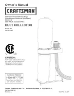
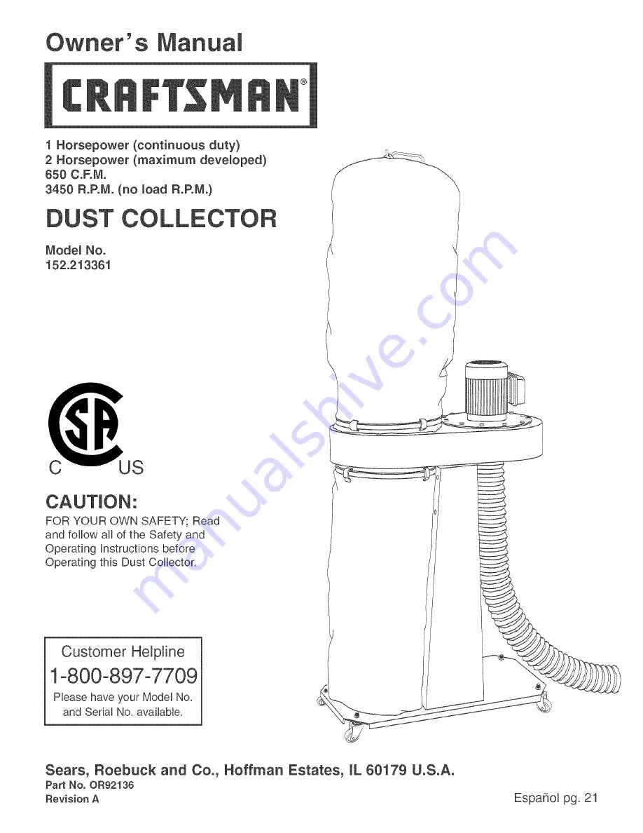
Page 21: ...ga COLE No de Mode_o 152 213361 C US PARA SU SEGURIDAD PERSONAL Lea y obedezca todas Ras tnstrucciones de Seguridad y Funcionamiento antes de accionar este CoUector de PoUvo Linea de Ayuda al Cliente 1 800 897 7709 Sirvase tenet listo su No de Modelo y No de Serie Sears Roebuck and Co Hoffman Estates JL 60179 U S A No de Pieza OR92136 Revisado A 21 ...

Page 22: ... Hoffman Estates IL 60179 Motor de Inducci6n HP CF de servicio continuo 1 HP CF maximo desarro Jado 2 Amperios 10 8 Voltios 120 Hertzios 60 RPM 3450 R RM R P M sin carga Tope Estandar de Ia Bolsa 30 micras Fondo Est_ ndar de Ia Bolsa 30 micras Manguera de Recobcci6n Manguera flexible de 4 pulg C F M pies c0bicos por minuto maximo Presi6n est_tica maxima en pulgadas de agua Capacidad de Ia Bolsa de...

Page 23: ...uando Ia herramienta electrica se encuentre en funcionamiento 7 8 NO FUERCE LA HERRAMIENTA a reaJizar operaciones para las cuales no fue disehada Realizara una labor mas segura y de meier calidad si se Heutiliza soHamente para realizar operaciones para Ias cuaHesfue diseSada UTJL_OE VESTJMENTA APROPIADA NO vista ropa holgada guantes corbatas ni art culos de joyer a Estos art cu os pueden quedar at...

Page 24: ...etre dentro de su boca u ojos o que permanezca sobre su piel puede pro mover la absorci6n de material da iino Utilice siempre protecci6n respiratoria adecuada y aprobada por NIOSH OSHA con ajuste correcto y lave las zonas expuestas con agua y jab6n 27 UTILICE UNA EXTENSION ELECTRICA CORRECTA Y EN BUEN ESTADO Cuando vaya a hacer uso de una extensJ6n electrica aseg0rese de utilizar una que sea Jo su...

Page 25: ...vo es un motor monofasico de 120 voltios Se envfa cabIeada para el fun cionamiento a 120 voltios Jamas conecte el aIambre verde a un terminal vivo SOLO UTJUCE UNA EXTENSION ELECTR_CA DE 3 NILOS QUE DISPONGA DE UN ENCNUFE DE CONEXION A TIERRA DE 3 MACHOS Y UN RECEPTACULO DE 3 POLOS QUE ACEPTE EL ENCNUFE DE LA MAQUINA REPONGA CUALQUtER CORDON DANADO O GASTADO tNMEDJATAMENTE Esta herramienta estb dis...

Page 26: ...ientes cuando no se encuentre en use y antes de rendir servicio cambiar bolsas destupir y Hmpiar 5 COLOQUE SIEMPRE el interruptor de energia en APAGADO antes de desenchufar el colector de polvo 6 PARA REDUCIR EL RiESGO DE CHOQUES ELECTRI COS no utilice a maquina a a intemperie No la expon ga a la Iluvia Aimac6neia baio techo Utiffcela para recoger materiaI seco soJamente 7 OBEDEZCA todos los c6dig...

Page 27: ...res de accesorJos varies NUMERO DE EX_STENCJA 21376 21377 21378 21372 21373 ConsuRar el catgJogo o la tienda Sears podrb recomendar otros accesorios no listados en este manual ConsuRe su Departamento de Ferreterfa de Sears mas cercano o el Catalogo de Herramientas Ebctricas y de Mane de Sears para otros accesorios No utilice ningOn accesorio a menos que haya Ie do cabal mente eJ Manual deJ Propiet...

Page 28: ...derse despues de que se hayan obtenido todas las piezas y estas hayan sido instaladas de manera correcta B F A K J C P A Ensamblado del soplador y del motor B Base C Ruedas pivotantes 4 D Soporte lateral 2 E Bolsa de filtro R Bolsa de recolecci6n 2 G Banda de sujeci6n H Soporte I Colgante de la bolsa de filtro J Vara de soporte inferior K Manguera flexible de 4 pulg h Abrazadera de manguera de 4 p...

Page 29: ...dmisi6n de 4 pulg B Manguera flexible de 4 pulg C Colgante de Ia bolsa de filtro D Bolsa de filtro E Bolsa de recolecci6n F Banda de sujeci6n G Ensamblado del soplador y el motor H Soporte lateral L Base J Rueda pivotante J B 29 ...

Page 30: ...g 5 2 3 hserte ei perno de Ia rueda pivotante a traves de uno de los cuatro aguieros A en Ia base B de los cuales no se iJustran tres Consulte la figura 5 Coloque la tuerca de pestaha hexagonaJ de 3 8 16 sobre el perno de Ja rueda pivotante y apriete Repita los Pasos 1 2 y 3 para los tres ensambJados restantes de rueda pivotante 1 2 A 3 4 Coloque la base A en posici6n erguida Consulte Ja figura 6 ...

Page 31: ...cabeza hexagonal de 5 16 18 x 3 4 pulg e nserte el torn llo a traves del soporte lateral roscando e tornilIo dentro de agujero roscado en el ensamblado del motor y el sopJador No Io apriete del todo Repita este proceso para los tres agujeros restantes Aprietelos firmemente Fig 9 1 2 3 4 5 Coloque el soporte A dentro de los dos soportes laterales B ASEGURESE DE QUE EL SOPORTE ESTE CONEOTADO A LOS S...

Page 32: ...mo coincidente del soporte inferior Enganche el ojaI en la boba de filtro superior sobre et gancho del colgante de la bolsa de filtro Consulte la figura 4 Fig 12 E E F 3 Inserte la banda de sujeci6n D a traves de todos los ojales de Ia bolsa de filtro E Coloque el extremo abierto de la bolsa de filtro sobre el borde superior deI tambor AsegOrese de que la banda de sujeci6n este co ocada en el cana...

Page 33: ...o indicado por la placa de notaciones deI motor Todas las conexiones de I nea deben hacer buen contacto El funcionamiento a baio voltaie periudi carb el motor NO EXPONGA ESTE COLECTOR DE POLVO A LA LLUVIA NI HAGA USO DE LA MAQUINA EN LUGARES HUMEDOS Fig 14 A B NTERRUPTOR DE ENCEND DO APAGADO E interruptor de ENCENDDO APAGADO se encuentra a costado det motor Para ENCENDER el cotector de polvo mueva...

Page 34: ... grande que sea adecuado debe tenderse Io mas lejos posible El tendido de una 34 manguera de diametro menor reducira considerablemente el C RM en la herramienta resultando en una recolecci6n de polvo limitada El use de botsas de recolecci6n y de filtro bajas en micras puede aumentar ia efectividad de su colector de polvo al eliminar las part culas finas de polvo Determine sJva a utilizar su Colect...

Page 35: ...grades utilizando una manguera de 4 pulg en diametro 0 84 MAS dos conectores en T de 90 grades 0 98 Total 1 82 Paso 3 Sume 2 5 para los factores de conexi6n a lamb quina y bolsa sucia 1 5 para conexiones 1 0 por bolsa sucia Paso 4 Totalice Ios tres cbJcutos antes mencionados Dicho total no debe exceder la presi6n estatica mb xima para su Colector de Polvo Po eiemp o4 4 totat del Paso 1 x 1 82 tota...

Page 36: ...or de 4 a 2 1 2 puIg 21352 Reductor de 3 a 2 puIg 21348 21351 21353 Reductor de 4 a 3 pulg Reductor de 3 a 2 1 2 putg Reductor de 2 1 2 a 1 1 2 puIg Abrazaderas de manguera cant 2 per paquete 21354 Abrazadera de manguera de 2 pulg 21356 Abrazadera de manguera de 3 pulg 21358 Abrazadera de manguera de 5 pulg 21355 21357 Abrazadera de manguera de 2 1 2 pulg Abrazadera de manguera de 4 puIg Campanas ...

Page 37: ... amcanza pbaa vemocidad Motor marcha demasiado camiente Apertura frecuente de fusiMes o disyuntores de circuito 1 Interruptor no oprimido Io suficiente o interruptor en el posici6n de APAGADO 2 Interruptor defectuoso 3 Capacitador defectuoso 4 Baja tensi6n de Ifnea 5 Motor defectuoso 2 3 2 1 2 3 1 Presione el interruptor hacia adentro 1 2 pulg o asegurese de que este an la posici6n de ENCENDiDO 2 ...

Page 38: ...X 3 4 pulg 4 IMPULSOR ARANDELA PLANA 5 16 pulg TORN_LLO DE CABEZA HEXAGONAL 5 16 8 X 3 4 pulg ENSAMBLADO DE LA CAJA DEL INTERRUPTOR COLOR NEGRO ABRAZADERA CAPACITOR 50 uf TORN_LLO DE CABEZA TRONCOCONICA 10 24 X 3 8 pulg 3 TORN_LLO DE CABEZA REFORZADA 10 24 X 3 8 pulg ENSAMBLADO DEL INTERRUPTOR PALANCA DEL INTERRUPTOR COLOR AMARILLO ETIQUETA DE ESPECIF CACIONES DEL MOTOR CORDON DE ENERGiA COLGANTE ...

Page 39: ...USTADO DE PIEZAS DEL COLECTOR DE POLVO PORTATIL _ IODELO NO 152 213361 26 z7_ 37 21 28C 28D 29 35 33 38 39 43 45 13 14 16 12 17 _ 18 39 ...

Page 40: ...s like vacuums lawn equipment and electronics call or go on line for the location of the nearest Sears Parts epair Center 1 800 488 1222 Anytime day or night U S A only To purchase aprotection agreement tU S A or maintenance agreement Canada or a product serviced by Sears 1 800o827 6655 U S A 1 800 361 6665 Canada Au Canada pour service en francais Para pedir servicio de reparaci6n a domicilio y p...

Reviews: