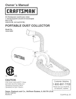
Craftsman 152.213351, Owner'S Manual
Download the Craftsman 152.213351 Owner's Manual for free from manualshive.com. This comprehensive manual provides step-by-step instructions, troubleshooting tips, and maintenance information for your Craftsman 152.213351. Don't miss out on this essential manual - get your free download now!
Share
Download


Reviews:
No comments
Related manuals for 152.213351
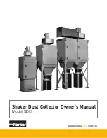
SDC
Brand: Parker Pages: 28
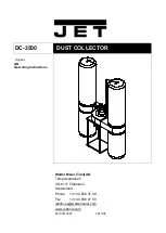
DC-3500
Brand: Jet Pages: 19
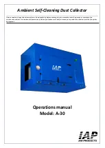
A-30
Brand: IAP Pages: 12
DC-1100A
Brand: Jet Pages: 15
DC-1200A
Brand: Jet Pages: 12
JCDC-1.5
Brand: Jet Pages: 20
JC-3BF
Brand: Jet Pages: 2
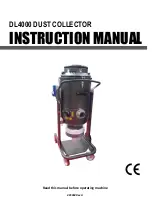
DL4000
Brand: National Flooring Equipment Pages: 32
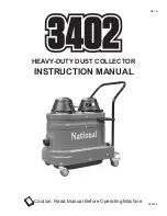
3402
Brand: National Pages: 28
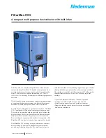
filtermax c25
Brand: Nederman Pages: 4
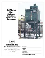
Gold Series
Brand: Farr Pages: 76
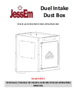
05151
Brand: JessEm Pages: 8
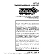
RPC-2
Brand: Zero Pages: 12
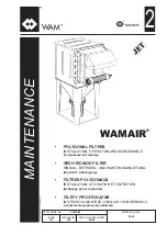
WAMAIR FPE Series
Brand: WAM Pages: 35
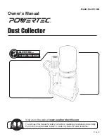
DC1080
Brand: PowerTec Pages: 16
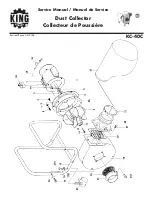
KC-40C
Brand: King Canada Pages: 2
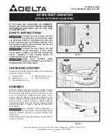
50-766
Brand: Delta Pages: 2
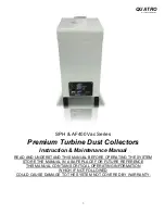
SPH Vac Series
Brand: Quatro Pages: 14


