Summary of Contents for 152.211640
Page 17: ...84N BENCH GRmNDER MODEL NO 152 211640 lO 38 40 17 ...
Page 18: ...18 ...
Page 34: ...34 ...
Page 35: ...35 ...
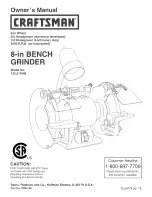
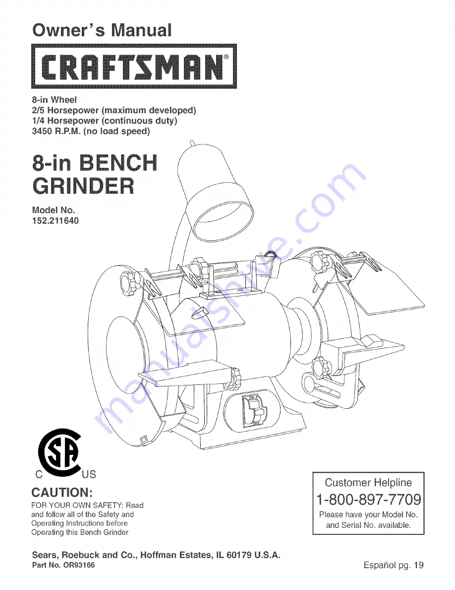
The Craftsman 152.211640 Owner's Manual is a comprehensive and invaluable resource for maximizing the potential of this powerful tool. Enhance your DIY experience and ensure optimal performance by downloading the free manual from our website. It provides step-by-step instructions, troubleshooting tips, and maintenance guidelines for a seamless user experience.
Page 17: ...84N BENCH GRmNDER MODEL NO 152 211640 lO 38 40 17 ...
Page 18: ...18 ...
Page 34: ...34 ...
Page 35: ...35 ...


