


OPERATOR’S MANUAL
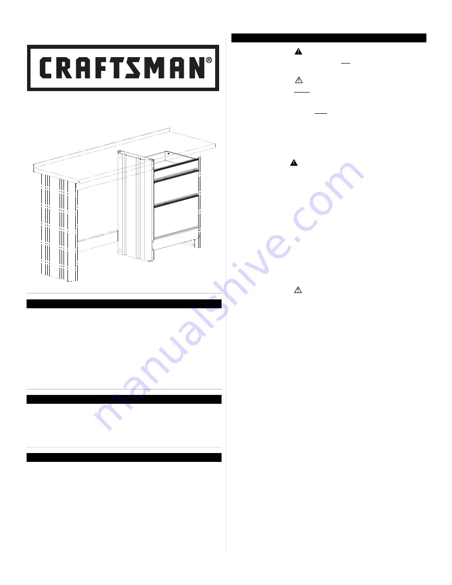
3-DRAwER AccESSORy
MODEL # 14926 & 14927
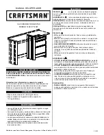
capacities
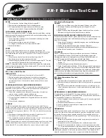
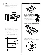
Locating Model # information
Model numbers and other information required for service parts is
located on a white label on the upper right hand corner of the unit.
Maintenance
• weight of the unit is 63 lbs.
• The maximum weight for Drawer should be no more than
35 lbs.
• Periodically the surfaces should be cleaned with a mild
detergent and water.
• Grease and oil can be removed with most standard cleaning
fluids. For safety, use a nonflammable cleaning fluid.
• Auto wax will preserve the unit’s luster finish. Apply the wax as to
a car. The wax will also help protect the unit against scratches.
• Lubricate the slides with grease or equivalent, (twice yearly).
F1872
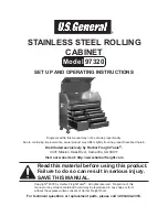
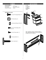
service parts
safety
DanGer
is used to indicate a hazardous
situation which, if not avoided, will result in serious injury
or death.
WarninG
indicates a hazardous situation which,
if not avoided, could result in serious injury or death.
caution
is used to indicate a hazardous situation
which, if not avoided, may result in minor injury, moderate
injury, or property damage.
caution:
Read and follow all Safety Rules and
Operating Instructions before first use of this product.
DanGer
•
Do not
stand on this product. you may fall which may
cause personal injury.
•
Do not
mount this product on a truck bed or any
other moving object. This may cause personal injury or
product Damage.
• Appropriately secure this product before moving it with
a forklift.
•
Do not
tow with power equipment. The product could
tip, which may cause personal injury or product damage.
•
Do not
step in the drawers. you may fall which may
cause personal injury.
WarninG
•
use appropriate safety
equipment when
using power and hand tools. Failure to do so may cause
personal injury or product damage.
•
use aDequate ManpoWer
when assembling
and moving this unit. Failure to do so may cause personal
injury or product damage.
•
Do not
alter this product in any manner. This may
cause product damage or personal injury.
•
unit Must Be
located on a level surface. The
product may become unstable and tip if stored or moved
on an un-level surface, which may cause personal injury
or product damage.
caution
•
Be carefuL
when opening more than one drawer.
The product may become unstable and tip, which may
cause personal injury or product damage.
Sears Brands Management corporation, Hoffman Estates, IL 60179 USA
caLL 1-800-366-7278 for service parts.
Refer to Service
Parts Drawing for full listing of Service Parts. Please provide the
Model Number when calling.