Craftsman 142.18882, Operation Manual
The Craftsman 142.18882 Operation Manual is an essential companion for owners of this top-of-the-line product. With its user-friendly format and clear instructions, this manual ensures seamless operation and maintenance. Download your free manual from manualshive.com today, empowering you with the knowledge you need for optimal performance.
Share
Download


Reviews:
No comments
Related manuals for 142.18882
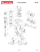
AG125
Brand: Makita Pages: 3
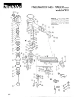
AF631
Brand: Makita Pages: 2
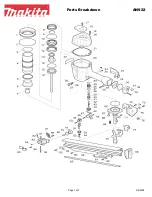
AN922
Brand: Makita Pages: 3
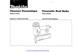
AF503
Brand: Makita Pages: 32
AN621
Brand: Makita Pages: 3
AN942
Brand: Makita Pages: 7
DBN500
Brand: Makita Pages: 24
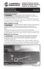
CHN71500
Brand: Campbell Hausfeld Pages: 2
CHN70600
Brand: Campbell Hausfeld Pages: 2
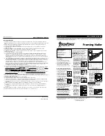
IronForce IFN2190
Brand: Campbell Hausfeld Pages: 12
CHN70800
Brand: Campbell Hausfeld Pages: 1

RH Series
Brand: D'Orly Pages: 11
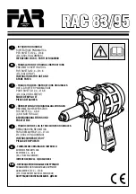
Rac 83
Brand: FAR Pages: 32
PET 25 A1
Brand: Parkside Pages: 44
PDRS 6.3 A1
Brand: Parkside Pages: 71
PAT 20-Li A1
Brand: Parkside Pages: 89
PSN90
Brand: Paslode Pages: 15
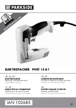
PHET 15 A1
Brand: Parkside Pages: 35


