background image

Summary of Contents for 132.24607

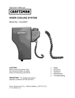
Page 1: ...this product read this manual and follow all Safety Rules and Operating Instructions IMPORTANT For replacement parts or assembly questions call 800 320 MIST Safety Assembly Operation Maintenance Troubleshooting Sears Roebuck and Co Hoffman Estates IL 60179 U S A www oraftsman com ...

Page 2: ...n sumption will ensure optimal functionality of the system throughout maintenance intervals In the event that gasoline is mistakenly added to the water tank immediately stop using the cooling system and contact cus tomer service regarding the best way to dispose of your system If this Craftsman product fails due to a defect in material or workmanship within one year from the date of purchase retur...

Page 3: ...S D E REF QTY DESCRIPTION A 2 Hex Bolt 5 16 18 x1 1 4 B 2 Flat Washer 7 8 OD C 4 Cap Screw 5t16 8 x 3 4 D 8 Flat Washer 5 8 OD E 4 Nylock Nut 5 16 18 F 2 Dash Adapter Nuts G 4 Routing Clips H 1 Rubber Washer I 1 Dash Adapter Spacer J 4 Cable Ties ...

Page 4: ...AA Power Unit BB Misting Nozzle Assembly CC Mounting Bracket DD 9 16 Drill Bit BB ...

Page 5: ...want to reinstall seat springs without the bracket With bracket in place assemble springs to tractor using the new 5 16 x 1 1 4 bolts A and 5 16 flat washers B sup plied with the cooling system Tighten using moderate force Do not over tighten Step 2 With tractor seat still in the raised posi tion slide power unit in between the ears of the mounting bracket Power unit should rest on alignment tabs ...

Page 6: ...old the power unit AA to the mounting bracket CC WARNING Debris that may enter the supply tubes of the climate control system can cause undesirable performance results Use care completing the remainder of the installation to ensure optimal cooling effectiveness Step 1a Tractors w mounting locations Remove dust cap from rider s left mount ing location A screwdriver may be needed to pry dust cap fro...

Page 7: ... best location to mount misting arm Ensure that the chosen loca tion will not limit the functionality of the tractor or interfere with closing of the hood Mark desired location Prior to drilling take precautions to protect engine compartment from drill shavings Using supplied 9 16 drill bit DD drill hole through the dash at the desired mounting location Use caution not to damage anything in the en...

Page 8: ...second nut Tighten using moderate force Do not over tighten The assembly is now secure to the dash of the tractor NOTE If a hole was drilled in a dash not equipped with mounting locations Step Ib you will need to slide the dash adapter spacer I over hoses of the misting arm assembly BB prior to proceeding Slide one dash adapter nut F over supply lines and thread onto adapter until seated on the bo...

Page 9: ...nderneath tractor body along right side of chassis using care to avoid any potential interfer ence with tractor functionality IMPORTANT To ensure lines will not be damaged during tractor use it is recommended that you follow the exact path of existing electri cal supply lines installed on your lawn tractor Continue to feed lines through the engine compartment to the other side of the trac tor Ensu...

Page 10: ...tenance Minder If your tractor is not supplied with a Maintenance Minder proceed to step 12 NOTE The supply tube may be difficult to assembly to the filter body Wiping the barb with water may facilitate assembly Locate BLUE supply tube from power unit and BLUE supply tube from misting arm assembly Remove protective caps from the BLUE supply tube and filter attached to the BLUE tube Connect BLUE su...

Page 11: ...supplied with the power unit It will have blue and black wires attached to it Connect power unit male connector to tractor electrical connector just removed from Maintenance Minder in Step 10 Connect power unit s male connector to tractor connector until fully engaged Locking tab will hold connection together Proceed to Finalizing System Installa tion Verify all connections have been made and proc...

Page 12: ... tubes at the locations shown above See further instructions below NOTE Once the clip is installed to the supply line it may be slid along length of supply line to ensure proper attachment to tractor Continue mounting the next clip to the dash support on the right side of the tractor Install fin l clip on left side of dash sup port Pull supply lines through this clip to eliminate excess slack wher...

Page 13: ...ensure that you will obtain the best performance from your system Make sure all assembly instructions have been completed with all bolts and nuts tightened Make sure hose connections at the filters have been made and are fully engaged Make sure electrical connection has been made and is secure Check routing of supply lines and make sure they do not interfere with pedals pulleys or belts Check supp...

Page 14: ...uctions have been properly completed Remove fill cap on power unit and fill with DRINKING WATER through the basket filter until tank is filled to approximately 1 below the bottom of the basket filter Add 5 drops of household bleach to the water tank before the first use and every fourth use or once a month whichever comes first after that Replace cap and hand tighten This is a pressurized system a...

Page 15: ...en air can no longer be heard coming from misting head Remove fill cap on power unit and fill through basket filter with DRINKING WATER ONLY Replace cap and hand tighten ADJUSTING MIST DENSITY To optimize the cooling effectiveness of the system the adjustment valve offers unlimited variation of mist density from closed to fully open To increase the mist density turn valve counterclockwise To decre...

Page 16: ... val of every 4th filling or once a month which ever comes first Completely drain water tank See Emp tying Water Tank Fill tank with DRINKING WATER Be sure to always fill tank with basket filter in place Add 5 drops of household bleach to wa ter tank Replace cap and hand tighten Run system for 5 minutes with increased water flow The system is conditioned and ready for operation REPLACING FILTERS T...

Page 17: ... closed 2 Open adjustment valve 3 FilI cap not sealed 3 Properly seat fill cap 4 Drain plug not sealed 4 Properly seat drain plug 5 Water filter needs replaced 5 Replace water filter 6 Basket filter missing 6 Install basket filter Water streaming from 1 Water in air supply lines 1 Drain tank and run system until Misting Nozzle Tank Overfull only air is emitted from nozzle 2 Adjustment valve settin...

Page 18: ...NOTES 8 ...

Page 19: ...NOTES 9 ...

Page 20: ...iiances and items like garage door openers and water heaters 1 800 4 MY HOME ca aoy ime ornigh iiiiiiiiiiiiiii_ i 800 469 4663 U S A and Canada www sears com www sears ca Our Home For repair of carny in items like vacuums lawn equipment and electronics _11 anytime for the location of the nearest Sears Pa_s Repair Service Center 1 800488 1222 U S A 1 800469 4663 Canada _ sears com www sears ca TOpu...

Reviews: