background image

Operator’s Manual

MITER SAW STAND WITH 
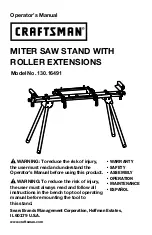
ROLLER EXTENSIONS 

Model No. 

130.16491

Sears Brands Management Corporation, Hoffman Estates,  

IL 60179 U.S.A.

www.craftsman.com

• WARRANTY

• SAFETY

• ASSEMBLY

• OPERATION

• MAINTENANCE

• ESPAÑOL


WARNING: To reduce the risk of injury, 

the user must read and understand the 

Operator’s Manual before using this product.


WARNING: To reduce the risk of injury, 

the user must always read and follow all 

instructions in the bench top tool operating 

manual before mounting the tool to  

this stand.

Summary of Contents for 130.16491

Page 1: ...tsman com WARRANTY SAFETY ASSEMBLY OPERATION MAINTENANCE ESPAÑOL WARNING To reduce the risk of injury the user must read and understand the Operator s Manual before using this product WARNING To reduce the risk of injury the user must always read and follow all instructions in the bench top tool operating manual before mounting the tool to this stand ...

Page 2: ... to obtain free replacement visit the web site www craftsman com This warranty is void if this product is ever used while providing commercial services or if rented to another person This warranty gives you specific legal rights and you may also have other rights which vary from state to state Sears Brands Management Corporation Hoffman Estates IL 60179 This miter saw stand has many features for m...

Page 3: ...posures varies depending on how often you do this type of work To reduce your exposure to these chemicals work in a well ventilated area and work with approved safety equipment such as those dust masks that are specially designed to filter out microscopic particles The purpose of safety symbols is to attract your attention to possible dangers The safety symbols and the explanations with them deser...

Page 4: ...e inform the user of important information and or instructions that could lead to equipment or other property damage if they are not followed Each message is preceded by the word NOTICE as in the example below NOTICE Equipment and or property damage may result if these instructions are not followed WARNING To ensure safety and reliability all repairs should be performed by a qualified service tech...

Page 5: ...perator s Manual To reduce the risk of injury user must read and understand operator s manual before using this product Eye Protection Always wear safety goggles or safety glasses with side shields and a full face shield when operating this product Safety Alert Precautions that involve your safety No Hands Symbol Failure to keep your hands away from the blade will result in serious personal injury...

Page 6: ...er saw stand It could tip over causing serious injury Do not permit children to use the stand unsupervised It is not a toy Be sure that all locking pins are in the set up position holes before using your miter saw and miter saw stand Take care when moving the stand especially when a miter saw is mounted Dress properly Do not wear loose clothing or jewelry Keep your hair clothing and gloves away fr...

Page 7: ...e the stand until the broken or missing part is replaced Failure to do so could result in possible serious injury WARNING Do not attempt to modify this stand or create accessories not recommended for use with this stand Any such alteration or modification is misuse and could result in a hazardous condition leading to possible serious injury UNPACKING Carefully remove all the parts and accessories ...

Page 8: ...ease return the stand to the place of purchase PACKAGE CONTENTS AND HARDWARE Item Description Quantity A Frame assembly including legs 1 B Quick release mounting bracket 2 C Cross support bar 2 D Support bar bolt 4 E Support bar washer 4 F Mounting bolt 4 G Mounting washer 4 H Spring washer 8 I Nut 8 J Extension bar locking knob 4 K Roller assembly locking knob 2 L Roller assembly 2 ...

Page 9: ...ock the other two legs the same way 4 Place the frame assembly on a flat surface as shown in Fig 4 MOUNTING A MITER SAW WARNING Failure to unplug the tool before attaching it to the stand could result in accidental starting and possibly serious personal injury WARNING To avoid serious personal injury always make sure that miter saws are fully supported and securely attached to a level work surface...

Page 10: ...ETS 1 Hold the quick release mounting bracket B by the handles 2 Position the area designated Z in Fig 7 on the frame assembly A 3 Press the handle down to mount the quick release mounting brackets B 4 Tighten the locking lever to lock the mounting brackets B Fig 8 Fig 7 Z A B Handle Kerf Fig 6 Fig 5 I H G F B Fig 8 locking lever Mounting Standard Miter Saws To The Stand NOTICE This allows for the...

Page 11: ...with non standard mounting holes on the cross support bars C Check the position and adjust the support bars slowly so that the mounting holes on miter saw are aligned with the slots on the cross support bars Fig 11 3 Use the miter saw mounting bolts F washers G spring washers H and locking nuts I to securely tighten the saw to support bars C 4 Tighten the locking nuts I to fully tighten the suppor...

Page 12: ...long workpiece the extension bars and rollers are needed The roller can be used as a stop guide or a single directional roller When using the roller as stop guide place the workpiece against the plate the roller assembly works as an stop guide to cut the workpieces to the length required Fig 15 When using the roller assembly as a single roller place the workpiece on the roller for convenient opera...

Page 13: ...cial solvents and may be damaged by their use Use clean cloths to remove dirt dust oil grease etc WARNING When servicing use only identical replacement parts Use of any other parts may create a hazard or cause product damage To ensure safety and reliability all repairs should be performed by a qualified service technician WARNING Keep the miter saw stand dry clean and free from oil and grease Alwa...

Page 14: ...MODEL NO 130 16491 The Model Number will be found on the Nameplate attached to the frame of the miter saw stand Always mention the Model Number when ordering parts for this tool To order parts call 1 888 331 4569 16491 Manual_Revised_1 0 ...

Page 15: ...support 2 5 2040701003 Roller 2 6 1020505001 Cover 4 7 1010101002 Screw 4 8 2040504004 Extension bar 2 9 1010122025 Screw 4 10 1021504001 Block 4 11 1021501002 Block 4 12 1010202004 Nut 14 13 2040107005 Base assembly 2 14 1020103002 Locking lever 2 15 1020801002 Connector 2 16 1021601002 Square block 2 17 1010402011 Spring bolt 2 18 1010118005 Brazier head screw 8 19 1010118006 Brazier head screw ...

Page 16: ...ss support bar 2 31 102102001 Screw 4 32 2040803001 Table base 1 33 1021601001 Square block 2 34 1021503001 Block 4 35 1010118004 Bolt 4 36 1010407001 Bolt 4 37 1010603017 Spring 4 38 1010202001 Nut 4 39 1010301001 Washer 4 40 1010602001 Shield ring 4 41 2040102001 Foot lever 4 42 1020906006 Footpad 4 43 1010303003 Spring washer 8 44 1010301007 Plain Washer 2 16491 Manual_Revised_1 0 ...

Page 17: ...VERTENCIA Para reducir el riesgo de lesiones el usuario debe leer y comprender el Manual de Operación antes de usar este producto ADVERTENCIA Para reducir el riesgo de lesión el usuario leer y seguir todas las instrucciones del manual de operación antes de montar la herramienta en este estante Sears Brands Management Corporation Hoffman Estates IL 60179 U S A www craftsman com ...

Page 18: ... Para detalles sobre la cobertura de garantía para obtener una devolución gratuita visite la página web www craftsman com Esta garantía se anulará si el producto ha sido usado mientras se proveía servicios comerciales o si se ha rentado a otra persona Esta garantía le otorga derechos legales específicos Puede que usted tenga otros derechos que varíen de un Estado a otro Corporación Sears Brands Ma...

Page 19: ...acto con estos químicos varía dependiendo de cuán frecuente realice este tipo de trabajo Para reducir el contacto con estos químicos trabaje en un área bien ventilada y con equipo con seguridad aprobada tales como máscaras para el polvo que estén especialmente diseñadas para filtrar las partículas microscópicas El propósito de los símbolos de seguridad es el de dirigir su atención hacia los peligr...

Page 20: ...vención de daño y mensajes informativos Le informan al usuario de información importante y o instrucciones que podrían producir daño al equipo u otra propiedad si no se cumplen Cada mensaje está precedido por la palabra NOTA como se muestra en el ejemplo aquí abajo NOTA Daño al equipo u o otra propiedad puede producirse si no se cumplen estas instrucciones ADVERTENCIA para asegurarse la seguridad ...

Page 21: ... de todo el rostro cuando utilice este producto Precauciones que involucran su seguridad No mantener sus manos alejadas de la sierra provocará lesiones personales graves No mantener sus manos alejadas de la sierra provocará lesiones personales graves No mantener sus manos alejadas de la sierra provocará lesiones personales graves No mantener sus manos alejadas de la sierra provocará lesiones perso...

Page 22: ... todo momento No cargue el estante para la sierra ingletadora con más de 330 libras Almacene adecuadamente No deje el estante para la sierra ingletadora al aire libre o en un lugar húmedo No se pare o suba en el estante para la sierra ingletadora Puede voltearse y causar una lesión seria No permita que los niños usen el estante sin supervisión Éste no es un juguete Asegúrese de que todos los perno...

Page 23: ...trica estén en buenas condiciones y con un ajuste y alineamiento apropiados Siempre mantenga sus manos alejadas del área de corte DESCRIPCION CONOZCA SU SIERRA INGLETADORA Fig 1 Fig 1 Perilla de cierre de barra de extensión Barra de soporte al través Seguro de manija Ensamblaje de rodillos Perilla de cierre de rodillos Marco de ensamblaje patas incluidas Soporte para montaje de Liberación rápida E...

Page 24: ...l uso y podría producir una condición peligrosa que genere una lesión seria DESEMPAQUE Retire cuidadosamente todas las partes y accesorios de la caja Asegúrese de que todos los artículos que se enumeran en la lista de empaque estén incluidos Inspeccione el estante cuidadosamente y asegúrese de que daños o ruptura no hayan ocurrido durante el envío No deseche el material de empaque hasta que haya i...

Page 25: ...de Liberación Rápida 2 C Barra para soporte al través 2 D Perno para barra de soporte 4 E Arandela de la barra de soporte 4 F Perno de montaje 4 G Arandela de montaje 4 H Arandela de resorte 8 I Tuerca 8 J Perilla de cierre de barra de extensión 4 K Perilla de cierre de ensamblaje de rodillos 2 L Ensamblaje de rodillos 2 16491 Manual_Revisado_18 0828 ...

Page 26: ...en la posición abierta y se escuche un click que señala que las patas están aseguradas en su lugar figura 3 3 Abra y asegure las otras dos patas de la misma manera 4 Coloque el marco de ensamblaje sobre una superficie plana como se muestra en la figura 4 MONTAJE DE LA SIERRA INGLETADORA ADVERTENCIA El no desenchufar la herramienta antes de montarla al estante podría provocar un arranque accidental...

Page 27: ...usando los pernos de montaje de sierra ingletadora F arandelas G arandelas de resorte H y tuercas de cierre I Fig 5 2 Una vez que la Sierra ingletadora está montada en los soportes de montaje colóquela sobre el estante Fig 6 INSTALANDO LOS SOPORTES PARA MONTAJE DE LIBERACIÓN RÁPIDA 1 Sostenga los soportes para montaje de liberación rápida B desde sus asas 2 Coloque el área designada como Z en la f...

Page 28: ...e montaje de liberación rápida B figuras 9 y 10 2 Coloque su sierra ingletadora con agujeros de montaje no estándares sobre las barras de soporte al través C Revise la posición y ajuste las barras de soporte lentamente de modo que los hoyos de montaje en la sierra ingletadora queden alineados con las ranuras en las barras de soporte al través figura 11 3 Use los pernos de montaje de sierra ingleta...

Page 29: ...o paradas positivas para cortes repetidos OPERACIÓN DE LOS RODILLOS Cuando trabaje con una pieza grande se necesitan barras de extensión y rodillos El rodillo se puede usar como una guía para parar o como rodillo individual para dirección Cuando utilice el rodillo como guía para parar coloque la pieza contra la placa el rodillo de ensamblaje trabaja como una guía para parar y cortar las piezas a l...

Page 30: ...ciales y pueden dañarse si se usan Use telas limpias para sacar suciedad polvo aceite grasa etc ADVERTENCIA Cuando repare use solamente partes idénticas de reemplazo El uso de cualquier otra parte puede crear un peligro o causar daño al producto Para asegurar la seguridad y confiabilidad todas las reparaciones deben ser realizadas por un técnico de servicio calificado ADVERTENCIA Mantenga el estan...

Page 31: ...DORA MODELO NO 130 16491 El Número de Modelo se encuentra en la placa de registro adjunta al marco del estante Siempre mencione el Número de Modelo cuando ordene partes para esta herramienta Para ordenar partes llame al 1 888 331 4569 16491 Manual_Revisado_18 0828 ...

Page 32: ...6 Rodillo de apoyo 2 5 2040701003 Rodillo 2 6 1020505001 Cubierta 4 7 1010101002 Tornillo 4 8 2040504004 Barra de extension 2 9 1010122025 Tornillo 4 10 1021504001 Bloque 4 11 1021501002 Bloque 4 12 1010202004 Tuerca 14 13 2040107005 Ensamblaje de base 2 14 1020103002 Seguro de manija 2 15 1020801002 Conector 2 16 1021601002 Bloque cuadrado 2 17 1010402011 Perno de resorte 2 18 1010118005 Tornillo...

Page 33: ...7001 Barra de soporte al través 2 31 102102001 Tornillo 4 32 2040803001 Base de mesa 1 33 1021601001 Bloque cuadrado 2 34 1021503001 Bloque 4 35 1010118004 Perno 4 36 1010407001 Perno 4 37 1010603017 Resorte 4 38 1010202001 Tuerca 4 39 1010301001 Arandela 4 40 1010602001 Anillo de escudo 4 41 2040102001 Manija de pie 4 42 1020906006 Pedal de pie 4 43 1010303003 Arandela de resorte 8 44 1010301007 ...

Page 34: ...Página 34 16491 Manual_Revisado_18 0828 ...

Page 35: ...Página 35 16491 Manual_Revisado_18 0828 ...

Page 36: ......

Reviews: