background image

Summary of Contents for 113.232210

Page 1: ...k side of the jointer base You should record both model and serial number in a safe place for future use tHl t i FORYOUR SAFETY READ ALL INSTRUCTIONS CAREFULLY 6 E INCH JOmHTER PL ER assembly e operating e repair parts L Luu u __ _ Sold by SEARS ROEBUCK AND CO Chicago iL 6068 4 U S A_ Part No SP5447 r_ ir_ r _ _c_r_ ...

Page 2: ...er footing and balance at all times i i_i _ln wo kingl order and in proPer adjustment and 15 MAINTAIN TOOLS WITH CARE alignment Keep tools sharp and clean for best and safest performance Follow instructionsfor lubricatingand I _ _ _ i _ _i _ _ i _ i NEVERSTAND ON TOOL OR ITS STAND i _i _ SH0_ ICHIL_ROOF _ Sed0us njU_could occur if the toot is tipped or ff i i_ maste_switchesilby removing star _ CU...

Page 3: ...ved pull the cutter guard open and let go If the guard doesn t smoothly swing closed contact Sears Service d Keep blades sharp Dull or knicked blades tend to pound and chew at the wood causing kickbacks e To avoid injury from thrown pieces make sure the blades are properly installed and the cutter blade wedge screws are tight 2 Plan Your Work to protect your eyes hands face ears Wear Safety Gogg e...

Page 4: ...Suddeniy pulled i nto the blade i I I D0 not wear gi0vesi 2 Removeaii ewelry and looseCi0thing 3 Tieback long hair_ _ 4_ Roll long sleeves above the elbow_ h_ To avoid inju yfrom accidental startingll always turn switch off_ remove switct_ key and unplug jointer planer before installing or removing any blade accessory or attachment or making any adjustments i To avoid an electrical shock make sure...

Page 5: ... back toward him by the rotating cutter knives 10 FENCE attached to the jointer planer ina more or less vertical position helps support and guide the workpiece as workpiece is pushe_lacross the cutter head 11 FREEHAND trying to use the toot without hold ing the workpiece firmly against the fence and table This can let the workpiece twist and kick back 12 LEADING END the end of the workpiece which ...

Page 6: ... Underwriters _ CAUTION To avoid motor damage this motor should be blown out or vacuumed frequently to prevent sawdust build up which will interfere with normal motor ventilation Connect this tool to a 120V 15 Amp branch circuit with a 15 Amp time delay fuse or circuit breaker Failure to use the proper size fuse can result in dam age to the motor If the motor fails to start turn the power switch t...

Page 7: ...ing reduced input voltage such as small size wire in the supply circuit or to overly long supply circuit wire Always check the connections the load and the supply circuit whenever motor fails to perform satisfactorily Check wire sizes and length with the Wire Size Chart shown to the right determine the minimum wire size A W G extension cord Use only 3 wire extension cords which have 3 prong ground...

Page 8: ...B Fence i 1 C Push Bocks ii i_ i i 2 D Siding Fence Guard 1 E Belt Guard t F Owner s Manual 1 G Legs 4 H Top Side Stiffener 2 I Bottom Side Stiffener 2 J Top End Stiffener 2 K Bottom End Stiffener 2 L Loose Parts Bag 507711 1 M Loose Parts Bag 508210 1 N Loose Parts Bag 508092 1 WARNING FOR YOUR OWN SAFETY NEVER CON NECTP LU G TOi_ POWER SOURCE 0 UTLET UNTIL ALLASSEMBLY STEPS ARE COMPLETEiANDYOU H...

Page 9: ...E K i i i _ i I ii_i i _ _ List of Loose Parts in Bag 508210 Item Description Qty O V Belt i 1 P Siding Guide Rod 1 Q Pulley 1 R Lock Knob _ 1 S iLoose Parts Bag 2 508091and 508093 O 9 ...

Page 10: ... _ i i Description Qty _H Spacer _ _ _ ill i i Washer380x 19 64x7 64 1 3 Retainerli _ _ i i O K Carriage Bolt3 8 16 x2 1 2 i _ 1 L Description L Switch Key i 1 iJJ G LIST OF LOOSE PARTS IN BAG 508093 Item Description Qty N i M Lllltppnltl_lllWUlWllimltlli g 0 S ...

Page 11: ...ation It must always be used 4 Fence Lock Knob Allows the fence to be repositioned and locked at any angle from 45 to 90 To lock turn the knob clockwise To unlock turn the knob counter clockwise 2 ON OFF SWITCH 3 CUTTER GUARD 5 Sliding Guard Knob Allows the fence to be repositioned at any location from the front to the rear of the tables and to be locked at that position To unlock turn the knob co...

Page 12: ...L _ ALONG THIS EDGE _ I 2SOC E _ J 9 16 SOCK_ iN I I I 6_ SOCKET EXTENSION 7ii6 OPEN END WRENCH 1 2 OPEN END WRENCH SHOULD BE NO GAP OR OVERLAP HERE WHEN 9 16 OPEN END WRENCH SQUARE IS FLIPPED OVER IN DOTTED POSITION I 3 4 OPENEND WRENCH THEJOINTER PLANER LEVELING FOOT 3 8 16 HEX NUT Q leg set hand TRUSS HEAD SCREW Q LOCK 114 20 WASHER HEX NUT STIFFENER STII ...

Page 13: ...ces of styrofoam on the floor and put the JointeriPlaner upside down on the cardboard as MOTOR CUTTER HEAD illustrated WARNING DO NOT TURN THE MOTOR ON UNTIL THE JOINTERiPLANER IS COMPLETELY ASSEM BLED AND TURNED RIGHTSIDE UP WITHiTHE i i_ LEVELING FEET SETTING AGAINSTTHE FLOOR_ _ IF THIS WARNING IS NOT FOLLOWED THE MOTOR MOTOR AND START SWITCH MAY BE BURNED OU_ YOUI MOUNTING COULD ALSO BE BADLYCU...

Page 14: ...NG THE CUTTERHEAD PULLEY FAILURE TO OBSERVE THiS IWARNING MAY CAUSE THE CUT TERHEAD TO MOVE OUT OF ITS PROPER POSI TION ALLOWING THE CUTTER KNIVES TO HITTHE METAL BASE CASTING MOTOR DRIVE PULLEY BELT 111 MOTOR CUTTERHEAD CUTTER PULLEY BOLTS q_DiIiiNim MOTOR PULLEY DRIVE BELT CUTTER PULLEY 14 ...

Page 15: ...holes in the leg set see illustration 3 Place a lock washer on each bolt Using your fingers screw the bolts through the leg set holes and into the mounting holes in the jointer planer Tighten the bolts securely using a 9 16 inch wrench 4 Using a 7 16 socket wrench tighten all nuts and bolts that hold the leg set together 5 Get another person to help you turn the jointer right side up so the leveli...

Page 16: ... not required check each locking screw on each wedge 5 32 HeX L wrench and tighten if necessary Hold the2inch pulley in a stationary position to prevent the Cut terhead from turning during this tightening proce dure WEDGE i _ i_ i_ii _ _ ii_i il_ii _ _ _i i i_ _ i_ _ _ _ CU I_ERHEAD ...

Page 17: ...nce to the jointer as illustrated below Rotate the cutter guard counterclockwise away from the fence and then release it The spnng tension on the guard must cause it to swing back against the fence if the guard does not swing back against the fence recheck your assembly procedure Do not use the jointer planer if the guard wilt not automati cally swing back against the fence and cover the cutter he...

Page 18: ...0 External Lock Washers two 32 x2 3 4 PaR Hd SCrews One i Belt Guard SLIDING GUARD SLIDING GUARD PLASTIC HEX NUT KNOB WASHER 112 PAN HD SCREW 2 314 EXTERNAL LOCKWASHER 10 LOCKWASHER 1 2 Illl lltlllllliflllillllllllllWIIIIIlllltlitltlllll Os PAN HD BE_ GUARD ROD i i 1 2 NUT ...

Page 19: ...E_ GUARD j 2 3 4 LONG PAN HD SCREW 5 Attach sliding guard to fence with two pa n head WASHER screws and Iockwashers _ i _ _ CONCAVE SIDE UP 6 Place one Sliding Guard Washer concave side DOWN on support rod 7 Drop sliding guard onto rod place other washer concave side UPon rod screw on Sliding Guard Knob LOCKWASHER WASHER CONCAVE SIDE DOWN 1 4 PAN HD SCREW 19 ...

Page 20: ...know your _ ointerwplaner J ID KEEP F UP AGAIN WH L WARNING FOR YOUR OWN SAFETY TURN SWITCH i_i OFF AND i REMOVE PLUG FROM POWER SOURCE OUTLET BEFORE MAKING ANY ADJUSTMENTS 4 4S_FENCE _ STOP STOP ...

Page 21: ...tch NOTE Key is made of yellow plastic b To turn the tool on insert your finger under the switch lever and pull the end of the switch out C i ii1_ To turn the tool OFF _ PUSH the lever in Never leave the machine unattended until it has come to a complete stop d To lock the switch in the OFF position hold the switch IN with one hand REMOVE the key with the other hand WARNING FOR YOUR OWN SAFETY ALW...

Page 22: ... OUTFEEDTABLE To tilt fence loosen the fence 10ckknob and slid ing guard knob and pull the stop out Tilt to desired angle and tighten both knobs d To set fence at 90 to tables loosen the two knobs titt fence so the stop springs back into place Tilt fence back so the stop rests on the table Hold fence down on outfeed table and tighten both knobs e i 45_ Fence Stop positions the fence at 450to the t...

Page 23: ...er direction until fence is square with infeed table NOTE If you cannot square fence by turning knurted sleeve loosen three screws A and ad just fence square to table c Tighten 90 stop iockscrew and both fence lock knobs CUTTER GUARD dr If 90 reading on tilt scale does not line up with top surface of the slide bracket loosen screws holding scale and move it tighten screws A KNURLED SLEEVE 45 STOP ...

Page 24: ...CROWNED I it is indication that the oUTWARD adjusted _ If thecut edge or surface o the workp ece is CON _ J INFEED TABLE LOW CAVE it is an indicati0n that the OUTWARD END _ _ of the INFEEDtable is LOW and must be adjusted _TO check the infeed table to determine the out of cutter uard touches the OUTFEED TABLE INFEED TABLE ...

Page 25: ...entation exposed as you turn the cut L _ _ _ _ J___F _ ter guard counterclockwise This will hotd cutter _ 7_ _ _ guard open _ _ _ _ VIEW FROM BACKSIDE JOINTER PLANER b Wrap a peice of cardboard around cutterhead to protect your fingers and the blades secure cardboard with a piece of tape CARDBOARD c Using a 1 2 inch open end wrench Ioosenthe Iockboits 1 2 turn under the section of the table that i...

Page 26: ...dedso you may attach an auxiliary fence to the front of the cast iron fence An auxiliary fence should be used anytime you joint boards _ ider than 4 1 2 incheS_The auxiliary fence should be made from a smooth straight board and cutto a widtPithat witt cause the auxiliary fence tO be no more than 1 inch narrower than the board being jointed_ i _ Attach theaUxiiiary fence as i lustrated MOUNTING HOL...

Page 27: ... Do not wear gloves b Remove all jewelry and loose clothing c Tie back long hair d Roll long sleeves above the elbow 6 To avoid burns or other fire damage never use the jointer p_aner near flammable liquids vapors or gases 7 To avoid injury from slips and jams a Use this jointer planer to cut only wood b Plan your hand placement so your fingers will not be anywhere a sudden slip could cause them t...

Page 28: ...ue feeding in this manner hand over hand until causes a rippled cut i _ makesit difficult to guide the workP _ _ccuratety anti could be hazardous JOtNTING WOOD THAT IS THICKER THAN 3 INCHES _ i _ Always feed WITH THE GRAIN whenever possible If the nature of the workpiece iS such that it must be fed AGAINST THE GRAIN take very light cuts and feed s_owly ROTATION WiTH THE GRAIN AGAINSTTHE GRAIN ROTA...

Page 29: ...ld down push blocks flat on topof workpiece _ _ _ _ and push the workpiece down againstthe tabieto pro i i i _ __ _ vide aqual cut and minimIzethe chance ofa kickback Hold down pressure must atso be sufficient to prevent _ i _ __ hotd down push bock sliding or slipping Onthe top face 1 i t _ of workpiece when advancing workpiece Over cutter JOINTING WOODNARROWER THAN3 INCHES head _ i Use a hand ov...

Page 30: ...sired angle lock fence in positionusingfence lock knoband slidingguard knob pieces of wood 3 inches or wider hold the board firmly doWn on both tables and firmly against the fence asitiustrated with your hands on the side and top of the workpiece keep fingers close together CHAMFER BEVEL BEVELING WOOD NARROWER THAN 3 INCHES 30 ...

Page 31: ...t or damaged in any way have it replaced immediately IIH ll II II ll I I lllll If disassembly of the motor is necessary it should be returned to your nearest Sears retail or mail order store in order to prevent voiding the guarantee NOTE The speed of this motor cannot be regulated or changed Motors used on wood working tools are particularly sus ceptible to the accumulation of sawdust and wood chi...

Page 32: ...R SAFETY GOGGLES hand _gent_y pry up each Wedge using a small pry bar Remove wedges andknives knives is as foliows a Locate the two lifter screws under the knife b Hold the cutterhead pulley firmly with one hand to prevent the cutter head from turning c Using a i18 Hex L wrenchl turn one of the lifter screws 1 4 of a turn counterclockwise d Now turn the other lifter screw 1 4 of a turn countercloc...

Page 33: ...notebook paper on top of the outfeed table _ __ b Put the head of a squareon topof the paper The end of the square must extend past the end of the outfeed table and above one end of the cutterhead i i c Turn the lifter screws counterclockwise to raise the knife until if just touches the square d _To check your adjustrnenti I gently turn the cut terhead back and forth by moving the cutterhead pulle...

Page 34: ...UTTERHEAD PULLEY TO PREVENT ACCIDENTAL ROTATION OF THE CUTTERHEAD _ __ SHARPENING CUTTER KNIVES The knives can be honed individually withan ordinary oilstone Make sure your oilstone is not worn in the center It must be flat Besure to remove the burr on the flat side 11 16 IN NEW BLADE if the knives are nicked they must be replaced or re ground They can be regrounded several times until they become...

Page 35: ... of the wood 3 If guard does not return to its REST position remove the guard by following steps 1 thru 6 above Make sure the spring is installed correctly and not broken If the spring is broken it must be replaced Reassemble the guard and spring and test again by following steps 1 and 2 If guard still does not return to its REST position consult your local Sears Retail Store before using the join...

Page 36: ...d 1 Re adjustblades seeManienancesecton surface I other i i 2 i Feedingwoodtoo fast 2 Feed wood slower Kickl_cks I 3 Cuttingknives am settoo h gh 3 Re adjustbades see Ma ntenance sect on i i I _aboVeouffeed table ortheyare _ not leveled withoutfeed table i lnfeed tab e out of adjustment Re adjust infeed table see Gett ngTo Know Your Jointed P aner section 11 Tighten Iockbolts l 5 16 181ockbotloose...

Page 37: ...d Electrical Requirements section 3 Request a voltage check from the power company 1 Low voltage willnot trip relay 2 Windings burned outor open 3 Starting relay notoperating 4 Drive belt tension to 0 h gh 1 Motor overloaded 2 Impropercooling Air circulationrestricted through motordue to sawdust accumulating inside of motor I 1 Request voltage check from the power company 2 Have motor repaired or ...

Page 38: ...31 i_ i_i z_ LIST FOR CRAFTSMAN 6 1 8 INCH JOINTER PLANER MODEL NO 1113 232210 FENCE ASM 34 _ SEE FIG 2 32 TABLE ASM SEE FIG 3 ui u _ _ _ _ i ii SEE FIG 4 _ ii 15 14 13 12 9 _t 10 1 FIGURE 1 i i 5 ...

Page 39: ...x 5 16 18 x 1 3 4 Spacer Washer 17 64 x 3 4 x 7 64 Lockwasher 1 4 Screw hex Hd 1 4_20 x1 2 Lockwasher Ext t0 Screw Pan Hd 10 32x 3 8 Clamp Cord Pulley Motor Screw Hex ad 5 16 18 x 3t4 Standard Hardware item May Be Purchased Locally i Key Part Description No No i i 22 STD551031 23 818098 24 806196 3 25 8 6573 26 STD328012 27 STD304210 28 818100 29 808277 1 30 62331 31 47624 32 STD551037 33 132 275 ...

Page 40: ...5 STD51 i102 Description i Guard Cutter Screw Pan Hd 10 32 x 1 4 Key No 11 12 13 4 15 16 17 Part No STD55 010 STD510802 STD551150 STD541050 818104 21622 67020 Description i l Washer t3 64 x 1 2 x 3 64 Screw Bind Hd 8 32 x 1 4 Lockwasher 1i2 Nut Hex Jam 1 2 13 Rod Sliding Guide Washer Sliding Guard Knob SlidingGuard i _ 40 ...

Page 41: ... STD551025 Description Table Front Linkage Assembly Washer 11 32x 11 16x t 16 Lockwasher 5 16 Screw Hex Hd 5 16 18x 1 1 4 Screw Hex Hd 4 20 x t 2 Washer 17 64 x47 64 x 1 16 Standard Hardware Item May Be Purchased Locally I Key No 10 11 12 13 14 Part No 111 I 21812 21422 21635 21219 21218 60388 817734 816871 Description Plate Tension Spacer Dovetail Screw Special Guide Male Guide Female Nut Self Th...

Page 42: ...URE 4 CUTTER ASSEMBLY i 1 _ 3 Stock Item May _ S_cure Key Part Description No No 8 9 0 11 _ 2 21450 21632 9 2293 60116 60118 i I Head Asm Complete Cutter Wedge I Blade Screw Soc Cap 10 32 x 3 4 Screw Ftat Hd Soc 10 32x 2 ii_ _i_ _ _ i_ i i_ _ Retail or Catalog Order Houses ...

Page 43: ...sher Ext 10 STD51 t103 Screw Pan Hd 10 32 x 3 8 8037091 Connector Wire 816880 i Bezel Switch 9 22256 i t Key Switch i i Key No 8 9 10 11 12 13 Pan No 1 816274 2 817399 6 816560 1 816881 820075 816560 2 Description i i Screw Pan Hd 10 x 1 Relay Model 01 Lead Jumper Housing Switch Capacitor Dry Film Lead Jumper Standard Hardware Item May Be Purchased Locally 1 Stock Item May Be Secured Through The H...

Page 44: ...umber Not by Key Number FIGURE 6 LEG SET ASSEMBLY Key Part No No ii i 7 8169O8 8 805589 5 9 STD551225 10 STD541025 50771 Description Stiffener Lower Screw TrussHd 1 4 20x 1 2 Lockwasher Ext 1 4 Nut Hex 1 4 20 Bag of Loose Parts Not Illustrated ...

Page 45: ...NOTES 45 ...
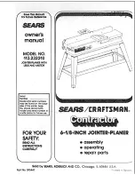
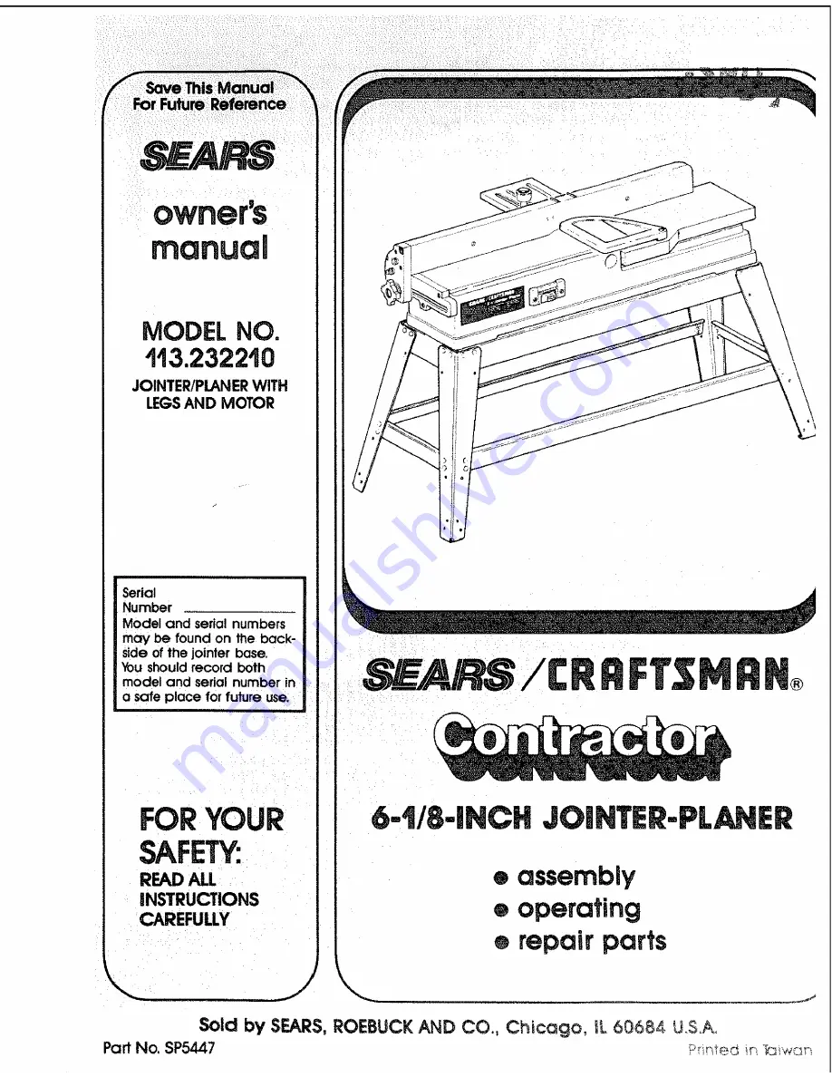
Page 46: ... you call or visit The model number of your 6 I 8 inch jointer planer will be found on a plate attached to the base WHEN ORDERING REPAIR PARTS ALWAYSGIVE THE FOLLOVvlNG INFORMATION PARTNUMBER MODEL NUMBER i 113 232210 PARTDESCRIPTION NAME OF ITEM 6 I 8 INCH JOINTER PLANER Allpartslisted may be ordered from any Sears ServiceCenter and most Sears stores If the partsyou need are not stocked locally y...

Reviews: