background image

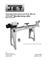
Summary of Contents for 113.228162

Page 1: ...umber may be found under belt guard You should record both model and serial number in a safe place for future use CAUTION O Read GENERAL and ADDITIONAL SAFETY INSTRUCTIONS cerefully 2 INCH WOOO TURNING A THE assembly operating repair parts Sold by SEARS ROEBUCK AND CO Chicago IL 60684 U S A t No SP4938 _e_ _ ...

Page 2: ...USE RIGHT TOOL Don t force toot or attachment to do a job for which it was not designed 11 WEAR PROPER APPAREL DO not wear loose clothing gloves neckties or jewelry rings wristwatches to get caught i_ moving parts 21 NONSLIP footwear is recommended Wear protective hair covering to contain tong hair Roll long sleeves above the elbow 12 USE SAFETY GOGGLES Head Protection 22 Wear safety goggles must ...

Page 3: ...the switch key j Never operate the Lathe with protective cover on the unused shaft end of the motor removed Hang your turning tools on the wall toward the tail stock end of the Lathe Do not lay them on the bench so that you must reach over the revolving workpiece to select them 8 Keep firm hold and control of the turning toot at aH times Speciat caution must be exercised when knots or voids are ex...

Page 4: ... NOT BE CONVERTED TO OPERATE ON 230VOLTS EVEN THOUGH SOME OF THE RE COMMENDED MOTORS ARE DUAL VOLTAGE THESE MOTORS HAVE BEEN FOUND TO BE ACCEPTABLE FOR USE ON THIS TOOL HP RPM VOLTS CATALOG NO 1 3 1725 110 120 1282 t 2 1725 110 120 1278 2 1725 110 120 1279 1 2 1725 1t0 120 1289 CAUTION Do not use blower or washingmachine motors or any motor with an automatic resezoverload protector astheir use may...

Page 5: ... Carriage 1 4 20x 1 3 4 4 Spur Center 1 Point Center 2 Cup Center I Cord Clamp 2 Grip 4 Switch Key 1 Lookwasher Ext 10 4 Nut Lock 4 20 4 Nut Hex 1 4 20 4 Nut Sq 1 4 20 3 Nut Hex Heavy 3 4 16 1 mine the minimum wire size A W G extension cord Use only 3 wire extension cords which have 3 prong grounding type plugs and 3 pole receptacles which accept the tools plug Extension Cord Length Wire Size A W ...

Page 6: ...e as shown 6 Set large tool rest in tool rest holder and install locking handle as shown REST Slide tailstock assembly onto the tube and install tailstock ram spindle lock handle Notice location of keyed way i_ spindle with studnut TAILSTOCK RAM SPINDLE KEYED HEADSTOCK END _ STUDNUT HANDLE LOCKNUT TAILSTOCK ASSEMBLY 8 On the backside of the tailstock asse ruble the locking devices as shown 5 Attac...

Page 7: ...ion Lathe on bench and insert two bo_ts through holes in headstock but do not screw on the nuts 3 Position the Lathe so that the bed is paralleltothe front of the bench Check the foot if the bottom of the foot is not fiat on the surface of the bench loosen the screw in the foot tap the screw to loosen the Iocknut inside Turn the foot so it is flat on the bench and tighten the screw 4 Mark the loca...

Page 8: ...ace a straightedge such as a piece of wood metal or framing square across the pulleys to see if they are in line with each other tf they are tighten the other two motor mounting bolts If they are not in line loosen the two motor bolts and move the motor sideways tighten the boJts 15 Find four pan head wood screws t 2 long from a mong the loose parts 16 Attach the belt guard plate to the bench with...

Page 9: ...until secure J f 3 Insert spur center into head stock spir_dle and cup center into tai stock ram NOTE Do not drive or hammer centers into spindte or ram as removal may be difficult Use a soft hammer or block of wood and give them a gentle tap 4 To remove spur center from spindle hen the spindle pulley with one hand and using a wrench or pair of pliers turn the hex nut counterclockwise until center...

Page 10: ... have removed the switch key Do net cycle the motor switch on and off rapidly as this may cause the faceplate or sanding disc to loosen In the event this should ever occur stand clear of the face plate or sanding d_sc until it has come to a complete stop retignten it 4 To lock switch in OFF position HOLD switch IN with one hand REMOVE key with other hand WARNING FOR YOUR OWN SAFETY AL WAYS LOCK TH...

Page 11: ...K 1 0 ON OFF SWITCH HEADSTOCK I BELT GUARD LOCK Locks the hinged part of the guard during operation 2 INDEX PIN Engages with the spindle pufley to determine equal spacing for cuts for fluting or reeding or for dividing face plate work DO NOT USE FOR REMOVING FACEPLATES 3 SPINDLE LOCK HOLE For removing faceplates or sanding discs insert a setscrew wrench large na_I or bolt in the hole to hold the s...

Page 12: ...re Jn line tighten the setscrew in the headstock and the screw in the end Df the tailstook 3 16 SETSCREW WRENCH HEADSTOCK F 3116 SETSCREW 1 FOOT TAI LSTOCK _ _ANDWH_ EW 12 TAILSTOCK _ supports the workpiece for spindle turning The tailstock contains a brass screw which bears against the key on the underside of the bed This screw Dre_ vents excessive looseness rocking back and forth of the tailstoc...

Page 13: ...e power cord is removed from the outlet 2 With the belt guard raised rotate the motor pulley COUNTERCLOCKWISE with your left hand while pushing on the belt with your right hand 3 Continue to rotate the pulley while pushing on the belt until it climbs down into the third step of the motor pulley 4 Now rotate the spindle pulley C LOC KWtS E with your right hand while pushing on the belt with your le...

Page 14: ...e cup center and drive the spur center into the other end of the wood Make sure the spurs are in the saw cuts Remove the spur center 7 Make sure t he centers and the hole in the spindle and the tailstock ram are clean insert the spur center rote the headstock and the cup center into the tailstock and tap them in lightly with a piece of wood Do not drive them in 8 Put a drop of oil or wax on the wo...

Page 15: ...es to keep the spindle from turning while you put a mark on the workpiece For example To focate the position of six spokes in a wheel 1 Pult the index pin outward and turn it so that the small cross pin slips into the slot This will allow the index pin to engage in one of the holes in the pulley and pre vent the spindle from turning_ 2 Adjust the tool rest approximately at the centeriine and make ...

Page 16: ...e being turned travels under the chise_ edge tike an endless belt The second approach is toward the diameter of a workpiece as when turning the face of a faceplate turning or the side of a large shoulder on a spindle turning In this approach the surface being turned rotates like a disc under the chisel edge Sometimes the approach will be a combmat on of both t _ _ vCI RCUMFER ENCE J _ APPROACH_ DI...

Page 17: ...ed How to Position Toot Rest for CircumferenCe Scraping In scraping operations the too_ rest posit on is not as critica as it is for cutting operation s The chisel generally is held horizontally though it can be he_d_ at an _ngfe to reach into tight places Considering that the wife edge of the ehisef 8 CORRECT 9 yo DIGGING STOCK REMOVE D does the scraping sketches 9 and 10 show the results of too ...

Page 18: ...e burned When used for scraping however it should be backed off regularly to prevent overheating Unlike the gouge and skew the parting tool is seldom held with the bevel against the work As the amount of stock removed is small a support for the bevel is not necessary The tool is simply fed into the work at an angle for cutting or pointed at the workpiece center for scraping It can be held easil_ i...

Page 19: ... a matter of individual liking but there are three genera ly accepted positions each best for certain types of operations ROUGHING OFF I Roughing offand other heavywork requires a firm grip and solid positioning of the chisel against the rest This is best obtained by the tool rest hand position illustrated The wrist is dropped down sothat the heel of the hand below the tittle finger acts as a slid...

Page 20: ...lly _scontinued until the cylinder is approximately 1 8 in larger than the desired finish size Roundness can be tested by laying the gouge on top of the work it will not ride up and down when cylinder is perfectly round_ FtRST CUTS MAKING SIZING CUTS Sizing c_Jts are useful to establish approximate finish size diameters at various points along a workpiece The work can then be turned down to the di...

Page 21: ... scraped with the spear point chisel or a three sided file CUTTING BEADS This requires considerable practice First make pencil lines to locate the tops highest points of two or more adjoining beads Then make a vee groove at the exact center between two lines and down to the desired depth of the separation between the beads 8e carefuf not to make the groove too wide or you will remove portions of t...

Page 22: ...posed turning This can be laid out on a suitable sheet of paper and should be to full size Next preparethe turning stock by squaring it up to the size of the largest square or round section in you r plan The stock can be cut to the exact length of the proposed turning but in most cases itis best to leave the stock a little long st one orboth ends to allow for trimming DIAMETERS i _ _4 _ SIZING CUT...

Page 23: ... measuring the sizing cuts Each semi circular cut is held against the workpiece instead of using the calipers USING DIAMETER SIZING GAUGE 24909 Production work can be further speeded by the use of the Diameter Sizing Gauge 24909 to take the place of caliper measurements The positions of the ar ms are set to indicate the various sizing cuts to be made Each arm is of such a length that it will drop ...

Page 24: ...OPERATaONS GUIDE BLOCKS FOR SCRAPING OPERATIONS A guide block can be clamped to a chise_ to limit the depth of cut and aid in the production of perfect cylinders tapers and facings on faceptate turnings SCraping methods must be used when the guide block is employed DRILLING For cross drilling flat sided work use a metal lathe drilt pad in the tailst ock and place a scrap board between the pad and ...

Page 25: ...sition DEEP RECESSES The first step is to remove as much wood as possible by boring into the center with the largest wood bit available This can be accomplished as illustrated Be careful to measure in advance the depth to which drill can be allowed to go BORING TO DEPTH Now remove the buik of the waste to rough out the desired recess by scraping w_ th the roundnose chisel or the gouge Remove up To...

Page 26: ...inder on this wooden chuck and recess the unworked end deep enough to form a perfect hole through the entire cylinder RECHUCKiNG Rechucking is the general term used to describe any additiona work mounting that is necessary to complete a turning project The method of working cylinders and the use of a plug chuck as already described are typical examples Another good example is the rechucking of a b...

Page 27: ...er method of rechucking is to use a shallow cup chuck which wilt not support the bail alone but must be used in conjunction with the tailstock When using the shallow chuck a wood block is fitted to the tailstock so that the ball can revolve upon it This block should be lubricated with beeswax or grease In using the shallow chuck method the ball is constantly shifted never more than 1 8 turn and al...

Page 28: ...bowl as shown in me finat illustration From this point on the work is simply a matter of turning down the bowl to any desired shape HOW TO TURN TYPES OF PLASTICS There are two general groups of plastics The first includes all phenol plastics moulded under heat and pressure Bakelite and Formica are examples In the second are all catalyst Setting plastics of various bases sold under such trade names...

Page 29: ...anded with the lathe running in second towest speed A large sheet of sandpaper is useful for smoothing cylinders All other sanding operations are done with a narrow strip of abrasive paper The best finishing grit is 3 0 for softwoods 4 0 for hardwoods SANDPAPER PER COVES WOOD FIBERS SANDPAPER 29 Worn 2 0 paper is often used and is the equivalent of 3 0 or 4 0 new paper The application of the sandp...

Page 30: ...TOR OUTLET SWITCH BLACK GREEN 2 POWER CORD lubrication Periodically lubricate the ram in the tailstock with N o 20 or No 30 engine oil MOTOR MAINTENANCE AND LUBRICATION 1 Thebearings in both end shields of the motor have been lubricated at the factory with correct lubricant No other part of the motor requires lubrication 2 Re lubricate motor bearings in accordance with the instructions on the name...

Page 31: ...ived and read com plete instructions for its use trouble shooting WARNING FOR YOUR OWN SAFETY TURN SWITCH OFF AND REMOVE PLUG FROM POWER SOURCE OUTLET BE FORE TROUBLE SHOOTING TROUBLESHOOTING CHART TROUBLE Motor will not run PROBABLE CAUSE 1 Defective On Off switch Defective switch cord Defective switch box receptacle 2 Motor protector Open only if your motor is equipped with an overload protector...

Page 32: ...Starting sw_tch not operating 2 Voltage too low to permit motoT to reach operating speed 3 Fuses or circuit breakers do not have sufficient capacity 1 Motor overloaded 2 Fuses or circuit breakers do not have sufficient capacity 3 Starting sw_tch not operating motor does not reach speed REMEDY t Have motor checked by qualified service technician Repair serwce is available at your nearest Sears stor...

Page 33: ...viewed from rear of saw using a flat blade screwdriver 2 Remove GREEN SCREW and iockwasher and insert screw through round metal terminal on _he end of the GREEN wire of power cord with leckvvasher between terminal and motor frame See iHus 3 ReinsertGREEN SCREW in the threaded hole Tighten securely 4 Insert terminal end of WHITE wire on spade _erminat r narked T4 on the motor Push terminal firmly u...

Page 34: ... c c_ 0 34 ...

Page 35: ... N e_ 6 Z LU O O LU k O Z m Z a k i O O 04 Z g k U O c _o a _6 N _z ILl D o O vZ O0 0 _o_ N o_o_oo o_o_ mo _oo_ _O _OOO_O_ OOOOOO_ _O oo_O _ O_ 0 _ E 23 o _E OZ 0 2 g _ I S _u u _ _ r E _ mm 35 ...

Reviews: