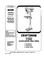
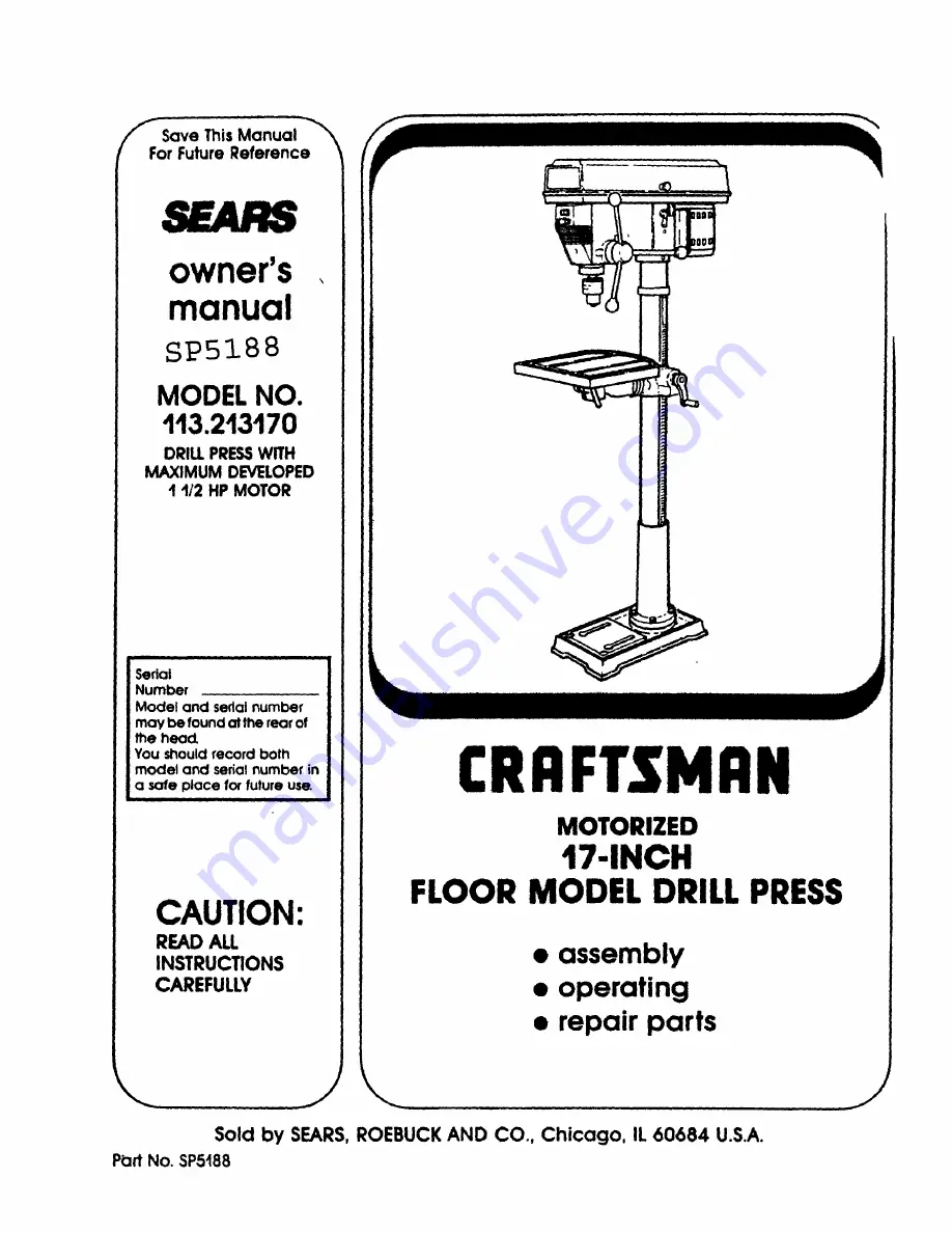
background image

Summary of Contents for 113.213170

Page 1: ...umber Model and sedai number may be found at the rear of the head You should record both model and serial number in a safe place for future use i i i CAUTION READ ALL INSTRUCTIONS CAREFULLY r CRRFTSMFIN MOTORIZED 17 1NCH FLOOR MODEL DRILL PRESS assembly operating repair parts Sold by SEARS ROEBUCK AND CO Chicago IL 60684 U S A P_rt No SP5188 ...

Page 2: ...igned for 11 WEAR PROPER APPAREL Do not wear loose clothing gloves neckties or jewelry rings wristwatches to get caughtinrnov ing parts NONSLIP footwear is recommended Wear protectivehair coveringto contain longhair Roll long sleeves above the elbow 12 USE SAFETY GOGGLES HEAD PROTECTION Wear safety goggles must comply with ANSI Z87 1 at all times Everyday eyeglasses are not safety glasses They onl...

Page 3: ...edly shift or your hand should slip c To avoid injury from parts thrown by the spring follow instructions exactly as given and shown in adjusting spring tension of quill always properly support your work so _twon t shift or bind on the tool Always posJt_on BACKUP MATERIAL use beneath the workptece to contact the left side of the column Whenever possfble position the WORK PIECE to contact the left ...

Page 4: ... to become com monplace Always remember that a careless frac tion of a second is sufficient to inflict severe injury The operatJons of any power tool can result in toreign ObleCts being thrown into the eyes whnch can result in severe eye damage Always wear safety goggles com ply with ANSI Z87 1 shown on Package before com mencing power tool operation Safety Goggles are available at Sears retanl or...

Page 5: ...rical Requirements 6 Unpacking and Checking Contents 7 Table of Loose Parts 8 Location and Function of Controls 9 Assembly 10 Assembly of Column and Table Hardware 10 Installing the Table 11 Installing the Head 11 Mounting Motor 12 Installing Motor Pulley 12 Tensioning Belt 12 Installing Belt Guard Knob 13 Motor Connections 14 Installing Feed Handles 14 Installing the Chuck 14 Installing Light Bul...

Page 6: ...ers Lalooratones and the Canadian Standards Assoclat on The ground conductor has a green lOCket and _S at tached to the tOol housing at one end and to the ground prong nthe attachment plug at the other end This plug requires a mating 3 conductor grounded type outlet as shown If the outlet you are planmng to use for th s power tool sof the two prong type DO NOT REMOVE OR ALTER THE GROUNDING PRONG I...

Page 7: ...ard Open the belt guard cover to find them WARNING IF ANY PARTS ARE MISSING DO NOT ATTEMPT TO ASSEMBLE DRILL PRESS PLUG IN THE POWER CORD OR TURN THE SWITCH ON UNTIL THE MISSING PARTS ARE OBTAINED AND ARE INSTALLED CORRECTLY 2 Remove the protective oil thaE is applied to the table and column Use any ordinary household type grease and spot remover WARNING TO AVOID FIRE OR TOXIC REAC TION NEVER USE ...

Page 8: ...escription Qty H Chuck 1 I Chuck Key 1 inlll i i i i L soL sPas a Item Description Qty K J Screw Hex HD M10 x 1 5 40 4 K Key Switch 1 L Knob 1 L M Screw Pan HD M5 x 0 8 12 1 M _ i i List of Loose Parts in Bag 507867 Item Description Qty N Idler Pulley Assembly 1 O Pulley Motor 1 P Belt V 112 x 27 1 Q Belt V 112 x 29 1 R Screw Hex HD M8 x 1 25 20 4 S Washer 21 64 x 7 8 x 3164 8 T Nut Hex M8 x 1 25 ...

Page 9: ...llows table to be rotated an various positions and locked 8 FEED HANDLE For moving the chuck up or down One or two of the handles may be removed f necessary whenever the workpiece s of such unusual shape that it interferes with the handles 10 TABLE REMOVED FOR CLARITY 14 15 16 9 CHUCK Holds drdl b tor other recommended accesso_ to perform desired operations 10 BEVEL SCALE Shows degree table is til...

Page 10: ... align holes in column support with holes in base 3 Locate 4 four 10ram Dia x 40ram long bolts see illustration in loose parts bag 4 Install a bolt in each hole through column support and base and tighten with adiustable wrench COLUMN SUPPORT 10ram OIA x 40mm LONG BOLT BASE 6 7 Locate table crank and supportlockin loose parts box Install support lock from left side into table support and tighten b...

Page 11: ...en table lock located under table by hand TABLE LOCK ii TABLE INSTALLING THE HEAD CAUTION The head assembly weighs about 55 pounds Carefully lift head 1 Remove protective bag from head assembly and discard Carefully lift head above column tube and slide it onto column making sure head slides down over column as far as possible Align head with table and base HEAD COLUMN HEAD LOCK 2 Usinga 5mm Hex L...

Page 12: ... the flat sur face on the motor shaft with the set screw in pulley 3 Make sure the pulley does not rest on the lower guard 4 Tighten the set screw using a 4 mm Hex L wrench FLAT SURFACE INSTALLING AND TENSIONING BELT WARNING TO AVOID INJURY DUE TO ACCIDEN TAL STARTING ALWAYS TURN DRILL PRESS OFF AND REMOVE SWITCH KEY BEFORE MAKING BELT ADJUSTMENTS 1 Place a straight edge such as a piece of wood me...

Page 13: ...counter clockwise until belt deflects approximately 1 2 inch by thumb pressure at its center 9 Tighten Belt Tension Lock Handles CAUTION Over tensioning belt may cause motor not to start or damage bearings 10 If belt slips while drilling readjust belt tension IDLER PULLEY BELT TENSION LOCK HANDLE TENSION HANDLE BELT GUARD KNOB Smm DIA x 12ram LONG SCREW BELT GUARD PAN HD INSTALLING BELT GUARD KNOB...

Page 14: ... termi nal next to copper post marked 1 on the motor Push terminal firmly until seated 6 Close motor connector box being sure that power cord is seated in strain relief groove and tighten box cover screws 7 Do not plug in power cable BLACK WIRE TO TERMINAL 1 COPPER POST GREEN WIRE TO GREEN SCREW STRAIN RELIEF GROOVE WHITE WIRE TO TERMINAL 4 SILVER POST laO_0R GREEN IGROUNO INSTALLING FEED HANDLES ...

Page 15: ... m i i 4 Unlock support lock and raise table so its about two 2 inches below tipof chuck 5 Turn chuck sleeve clockwise and open jaws in chuckcompletely 6 Turn feed handles cotanterclockwiseand force chuck against table untilchuck is secure SUPPORT LOCK CHUCK SLEEVE ...

Page 16: ...ble bevel lock with a 15116 wrench These adjustments are located under the table 4 Align the table square to the rod by rotating the table until the square and rod are in line 5 Retighten table bevel lock 6 Retighten set screw SCREW BEVEL LOCK BEVEL SCALE NOTE The bevel scale has been included to provide a quick method for beveling the table to approximate angles If precise accuracy is necessary a...

Page 17: ...DER TABLE 16 DEPTH SCALE LOCK 22 BEVEL SCALE lS 21 DEPTH TABLE LOCK INDICATOR QUILL AND SPINDLE ASSEMBLY INSIDE OF DRILL PRESS SPLINES J_ _ SPINDLE GROOVES RACK ___GE KEY TEETH 24 _ _ _ ARBOR CHUCK KEY H 14 DEPTH SCALE 13 TABLE 12 COLUMN 11 COLUMN 2 BELT TENS_N LOCK HANDLE 3 BELT TENSION HANDLE 4 HEAD LOCK 5 FEED HANDLE 6 COLUMN COLLAR 7 TABLE SUPPORT e TABLE CRANK 9 RACK 10 BASE 17 ...

Page 18: ...ss to floor See Additional Safety Instructions for Drill Presses 11 COLUMN SUPPORT Supports column guides rack and provides mounting holes for column to base 12 COLUMN Connects head table and base on a one piece tube for easy alignment and move ment 13 TABLE Provides working surface to support workpiece 14 15 16 17 18 19 20 21 22 23 24 25 26 DEPTH SCALE Shows depth of hole being drilled DEPTH SCAL...

Page 19: ...ds to tear the workpiece loose you can QUICKLY turn the drill OFF by hitting the switch with the palm of your hand To lock switch in OFF position hold switch IN with one hand REMOVE key with other hand WARNING FOR YOUR OWN SAFETY ALWAYS LOCK THE SWITCH OFF WHEN DRILL PRESS IS NOT IN USE REMOVE KEY AND KEEP IT IN A SAFE PLACE ALSO IN THE EVENT OF A POWER FAILURE ALL OF YOUR LIGHTS GO OUT OR BLOWN F...

Page 20: ...depth until the depth scale is readjusted DEPTH SCALE LOCK DEPTH SCALE MARK ANOTHER WAY DEPTH SCALE 1 With the switch OFF loosen the depth scale lock 2 Turn the depth scale clockwise untilthe depth scale indicator points to the desired drilling depth on the depth scale 3 Tighten the depth scale lock 4 The chuck or drill will now be stopped after traveling downward the distance selected on the dept...

Page 21: ...rill at a depth of 3 three inches See instructions for Locking chuck at desired depth 2 Align key holes in spindle and quill by rotating the chuck by hand See illustration 3 Insert key wedge into key holes 4 Tap key wedge lightly until the chuck and arbor fall out of spindle NOTE Place one hand below chuck to catch it when it falls out ml SPINDLE KEY HOLE QUILL KEY HOLE 1 ii ARBOR LOCKING COLLAR C...

Page 22: ...end of arbor slip _otoa notch in the spindle WARNING MAKE SURE THE RECTANGULAR END OF THE ARBOR HAS SLIPPED INTO THE NOTCH IN THE SPINDLE BEFORE GOING ON TO STEP 4 FAILURE TO FOLLOW THIS DIRECTION MAY ALLOW THE CHUCK TO COME LOOSE DURING OPERATION FLY OUT AND HIT THE OPERATOR SPINDLE ARBOR CHUCK SLEEVE CHUCK eDDY 4 Unlock support lock and raise fable so its about two 2 inchesbelow tip of chuck 5 T...

Page 23: ...e the Head or Table while the tool is running Before starting the operation jog the motor switch to make sure the drill or other cutting tool does not wobble or cause vibration If a workpiece overhangs the table such taht it wilt fall or tip if not held clamp it to the table or provide auxiliary support Use fixtures for unusual operations to adequately hold guide and position work piece Use the SP...

Page 24: ...t side of the column as illustrated WARNING TO PREVENTTHE WORKPIECE OR THE BACKUP MATERIAL FROM BEING TORN FROM YOUR HAND WHILE DRILLING POSITION THEM AGAINST THE LEFT SIDE OF THE COLUMN IF THE WORKPICE OR THE BACKUP MATERIAL ARE NOT LONG ENOUGH TO REACH THE COLUMN CLAMP THEM TO THE TABLE FAILURE TO DO THIS COULD RESULT IN PERSONAL INJURY WORKPIECE BACK UP MATERIAL _ _L For small pieces that canno...

Page 25: ... DUE TO SPRING RELEASE FOLLOW INSTRUC TIONS CAREFULLY AND WEAR EYE GOGGLES NOTCH JAM NUT OUTER BOSS CAP QUILL RETURN SPRING 1 With the chuck at its highest possible position turn the depthscale clockwise until it stops and tighten the depth scale lock This will prevent the quill drop ping while tensioning the spring 2 Lower table for additional clearance 3 Work from left side of Drill Press 4 Plac...

Page 26: ...LINES grooves in the spindle and the RACK teeth of the quill See Getting to Know Your Drill Press C _o Q I WIRING DIAGRAM i i Sears Recommends the Following Accessories 4 t 0 4 t Drill Bits See Catalog HoLd Down and Guide 9 2457 Drill Press Vises See Catalog Rotary Table See Catalog Drill Press Mortising Kit See Catalog Hole Saw up to 2 1 2 dia max See Catalog 5 pc Stop Collar Set See Catalog 15 P...

Page 27: ...talled 1 Spring has improper tension 1 Dirty grease oroilon the tapered insidesurfaceof chuck oronthe spindlestapered surface i i i i i i i i i i 1 Adjust tension See section ASSEMBLY TENSIONING BELT 2 Lubricate spindle See Lubrication section 3 Checking tightness of retaining nut on pulley and tighten if necessary 4 Tighten setscrews in pulleys 1 Change speed See section Getting To Know Your Dril...

Page 28: ...m 43 44 PARTS LIST FOR CRAFTSMAN 17 DRILL PRESS MODEL NO 113 213 70 47 48 49 5O 51 52 43 42 41 3O 32 28 28 31 26 27 FIGURE 1 25 24 23 3 5 4 1 13 14 22 21 15 2O 10 16 19 17 14 14 10 3 ...

Page 29: ... Spring Nut Hex 1 2 20 Nut Hex Jam 1 2 20 Key Pad No No 31 817778 3 32 817321 33 813317 8 34 813317 7 35 813317 6 36 60475 37 817329 38 STD375008 39 817694 40 63418 41 817337 42 STD835020 43 STD551031 44 817336 45 817328 46 STD840812 47 817298 48 STD841217 49 STD551150 50 817338 51 STD835016 52 817317 507865 507866 507867 507864 SP5188 Description Head w PoInter and Tr m Socket Bulb Asm Wrench Hex...

Page 30: ...ion iii i Ring Retaining Bearing Ball 25mm Spacer Bearing Belt V 1 2x29 Nut Pulley Pulley Spindle Insert Pulley Guard Pulley w Labels Screw RD HD Washer M6x 1 0 16 Key Part Description No No 10 11 12 13 14 15 16 17 817391 2 817331 817325 816755 3 818532 817332 STD315225 STD304270 i Screw Set M8 x 1 25 8 Pulley Motor Knob Screw Pan HD M5x 0 8 12 Pivot Idler Pulley Center Bearing Ball 15mm Belt V 1 ...

Page 31: ...09 2 817310 3 817311 4 STD315235 5 817314 6 817342 Part Description No i i Nut Lock Ring Locking Washer Bearing Ball 17ram Washer Rubber Tube Quill Key NO i 7 8 9 10 11 12 Part No Description i i i ii 817339 817340 817341 817326 817359 STD315255 i Key Chuck Chuck Arbor Key Drift Spindle Bearing Ball 25mm Standard Hardware item May Be Purchased Locally 31 ...

Page 32: ...817392 817777 2 iii i Screw Hex Soc Set M6x 1 0 10 Collar Rack Gear Helical Crank Table Clamp Table Screw Hex HD 5 8 11 x 1 1 4 Arm Table w Scale Key Part Description No No IIII 817361 817360 STD836040 817391 10 11 12 13 14 817285 15 817351 16 817294 17 817776 1 18 817349 19 817288 Base Support Column Screw Hex HD M 10 x 1 5 40 Screw Hex Soc Set M10x 1 5 12 Tube Column Rack Clamp Column Support Ta...

Page 33: ...NOTES 33 ...

Page 34: ...NOTES I I 34 ...

Page 35: ...NOTES 35 ...

Page 36: ...all orvisit The model number of your 17 inchDrill Presswill be found on a plateattached tothe rearof the head WHEN ORDERING REPAIRPARTS ALWAYSGIVE THEFOLLOWING INFORMATION PARTNUMBER PARTDESCRIPTION MODELNUMBER 113 213170 NAME OF ITEM MOTORIZED 17 INCH FLOOR MODEL DRILL PRESS All parts listed may be ordered from any Sears Service Center and most Sears stores If the parts you need are not stocked l...

Reviews: