Craftsman 113.20680, Owner'S Manual
The Craftsman 113.20680 is a versatile and reliable tool that helps you tackle DIY projects effortlessly. To make the most of this incredible product, ensure you have the Owner's Manual at hand. Download the comprehensive manual for free at manualshive.com to unleash the full potential of your Craftsman 113.20680.
Share
Download


Reviews:
No comments
Related manuals for 113.20680
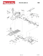
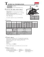
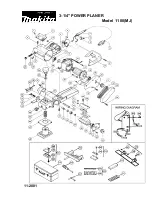
1902
Brand: Makita Pages: 2
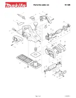
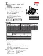
1912B
Brand: Makita Pages: 3
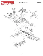
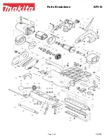
KP0810
Brand: Makita Pages: 3
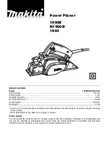
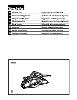
1900B
Brand: Makita Pages: 12
KP312
Brand: Makita Pages: 3
KP0800
Brand: Makita Pages: 8
KP0810
Brand: Makita Pages: 11
1911B
Brand: Makita Pages: 44
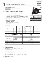
N1923B
Brand: Makita Pages: 60
M1902
Brand: Makita Pages: 19
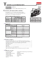
KP0800
Brand: Makita Pages: 56
BKP140
Brand: Makita Pages: 10
HG 1100
Brand: Makita Pages: 4
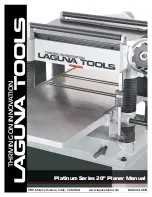
Platinum Series
Brand: Laguna Tools Pages: 42
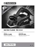
PEH 30 A1 ELECTRIC PLANER
Brand: Parkside Pages: 25
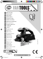
EP 900
Brand: Far Tools Pages: 74

PHA 12 B2
Brand: Parkside Pages: 132
5240
Brand: Oliver Pages: 59


