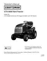
background image

Summary of Contents for 107.250050

Page 1: ...oss HP Briggs Stratton with 46 Mower For answers to your questions about this product call Sears Craftsman Help Line 1 800 65g 5g 17 Sears Brands Management Corporation Hoffman Estates IL 60179 U S A Visit our Craftsman website www craftsman com 1753800 Revision ...

Page 2: ......

Page 3: ...nd risks associated with mowers and how to avoid them This product and its approved attachments accessories are designed and intended only for lawn work or snow removal and are not intended for any other purpose It is important that you read and understand these instructions thoroughly before attempting to start or operate this equipment Save these original instructions for future reference Where ...

Page 4: ...duct s features and controls and maintenance information is included to help you get the most out of your equipment investment Be sure to completely read the Safety Rules and Information found on the following pages Also completely read the Operation section Children Tragic accidents can occur with children Do not allow them anywhere near the area of operation Children are often attracted to the u...

Page 5: ...uipment safely it is equipped with an operator present safety system Do NOT attempt to alter or bypass the system See your dealer immediately if the system does not pass all the safety interlock system tests found in this manual ThrownObjects This unit has spinning mower blades These blades can pick up and throw debris that could seriously injure a bystander Be sure to clean up the area to be mowe...

Page 6: ...n operating this unit 18 Data indicates that operators age 60 years and above are involved in a large percentage of power equipment related injuries These operators should evaluate their ability to operate the equipment safely enough to protect themselves and others from injury 19 Follow the manufacturer s recommendations for wheel weights or counterweights 20 Keep in mind the operator is responsi...

Page 7: ... increasing the possibility of roll over If the machine stops while going uphill stop the blades and back down slowly Avoid sudden turns TOWED EQUIPMENT RIDE ON UNITS I Tow only with a machine that has a hitch designed for towing Do not attach towed equipment except at the hitch point 2 Followthe manufacturer s recommendations for weight limit for towed equipment and towingon slopes 3 Never allow ...

Page 8: ...rther than necessary Ensure clamps grip hoses firmly over the filter after installation 12 Do not use gasoline containing METHANOL gasohol containing more than 10 ETHANOL gasoline additives or white gas because engine fuel system damage could result 13 If the fuel tank must be drained it should be drained outdoors 14 Replace faulty silencers mufflers 15 Maintain or replace safety and instruction l...

Page 9: ... thrown debris stay char ot deck edge a_l_ discharge DO not mow without _d_e _et_ii r entire gr_ss catcher in place Danger Rotating Blades No 1704277 reputation Hazard To avoid injury from rotating bllades stay _lear of deck edge _ Danger Rotating Blades Part No 1704276 Decal Cruise Control and Attachment Lift Part No 1723713 Transmission Release Part No 1730202 Figure 9 ...

Page 10: ...ns the tractor headlights on and off Figure 2 Reverse Mowing Option RMO The Reverse Mowing Option allows for mowing or use of other PTO driven attachments while traveling in reverse If you choose to mow or operate another attachment in reverse turn the RMO key after the PTO is engaged The L E D light will illuminate and the operator can then mow in reverse Each time the PTO is disengaged the RMO n...

Page 11: ...ustment UP arrow raises cutting height RIGHT arrow rotates the spout right etc When the adjustment indicator has reached the end of its travel release the switch holding the switch down will damage the motor D Cruise Control The cruise control is used to lock the ground speed control in forward Move the lever forward until the desired ground speed is reached To disengage the cruise control move th...

Page 12: ...specially with the engine at idle may cause battery discharge When not using the accessory plug it must be covered with the rubber plug to prevent moisture from causing a short circuiL Entrance of water into plug can cause a short circuiL Advanced Traction Control What is Advanced Traction Control Advanced Traction Control ATC is an exclusive feature of our transmissions that provides improved tra...

Page 13: ... with brake pedal NOT fully depressed parking brake OFF Test 4 Check Mower Blade Stopping Time Mower blades and mower drive belt should come to a complete stop within five seconds after electric PTO switch is turned OFF If mower drive belt does not stop within five seconds contact Sears Service Test 5 Reverse Mow Option RMO Check Engine should shut off if reverse travel is attempted if the PTO has...

Page 14: ...f starting or performance problems occur change fuel providers or change brands This engine is certified to operate on gasoline The emissions control system for this engine is EM Engine Modifications High Altitude At altitudes over 5 000 feet 1 524 meters a minimum 85 octane 85 AKI 89 RON gasoline is acceptable To remain emissions compliant high altitude adjustment is required Operation without th...

Page 15: ... START position NOTE If the engine does not start after repeated attempts go to BRIGGSandSTRATTON COIVI or call 1 800 233 3723 in USA NOTICE To extend the life of the starter use short starting cycles five seconds maximum Wait one minute between starting cycles Driving the Tractor 1 Sit in the seat and adjust the seat so that you can comfortably reach all the controls and see the dashboard display...

Page 16: ... in Reverse If an operator chooses to operate a PTO driven attachment in reverse the RMO system can be used To use the Reverse Mowing Option RMO turn the RMO key after the PTO is engaged The L E D light will illuminate and the operator can then operate the attachment in reverse Each time the PTO is disengaged the RMO needs to be reactivated if desired The key should be removed to restrict access t...

Page 17: ... When the adjustment indicator has reached the end of its travel release the switch holding the switch down will damage the motor Figure 8 Attaching a Trailer The maximum horizontal drawbar force allowed 444 Newton The maximum vertical drawbar force is 222 Newton This equates to a 396 Ibs 180 kg trailer on a 10 degree hill Secure the trailer with an appropriately sized clevis pin A Figure 10 and c...

Page 18: ...er comes first Clean more often in dusty conditions or when airborne debris is present Emissions Control Maintenance replacement or repair of the emissions control devices and systems may be performed by any non road engine repair establishment or individual However to obtain no charge emissions control service the work must be per formed by a factory authorized dealer See the Emissions Warranty C...

Page 19: ...g A dead battery or one too weak to start the engine may be the result of a defect in the charging system or other electrical component If there is any doubt about the cause of the problem see your dealer If you need to replace the battery follow the steps under Cleaning the Battery and Cables To charge the battery follow the instructions provided by the battery charger manufacturer as well as all...

Page 20: ... away from the spark plug 2 Remove the dipstick D Standard Oil Drain Plug 1 Remove the oil drain plug B Figure 13 Drain the oil into an approved container 2 After the oil has drained install and tighten the oil drain plug Optional Quick Oil Drain 1 Disconnect the oil drain hose G Figure 13 from the side of the engine 2 Turn and remove the oil drain cap H Carefully lower the quick oil drain I into ...

Page 21: ...level 3 Install and tighten the dipstick 4 Remove the dipstick and check the oil level It should be at the FULL mark F on the dipstick 5 Install and tighten the dipstick Servicing the Air Filter WARNING Fuel and its vapors are extremely flammable and explosive Fire or explosion can cause severe burns or death Never start or run the engine with the air cleaner assembly if equipped or the air filter...

Page 22: ...e mower gauge wheels can be placed in several positions depending on the height of cut When using higher cutting heights set the wheels in the lower position When using lower cutting heights set the wheels in the upper position 1 Remove the Iocknut A Figure 16 gauge wheel B washer C and shoulder bolt D Change position of gauge wheel to desired height 2 Insert shoulder bolt D through washer C gauge...

Page 23: ...e harness Place the attachment lift in the down position Remove the cotter pin A Figure 18 and lift chain B from the hook in tractor frame Repeat for the other side Remove the cotter pin and washer at the inner lift bracket C Figure 19 and disconnect the inner J bolt from the bracket Repeat for other side Pull the idler pulley lever D Figure 20 to release belt tension Remove belt E from PTO pulley...

Page 24: ...d lever and install the mower hitch on the tractor hitch brackets see Figure 22 NOTE When properly installed the spring loaded lever should seat fully underneath the brackets 4 5 6 7 Pull the idler pulley lever D Figure 20 to release belt tension Install belt E on the PTO pulley F Connect the inner J bolt C Figure 19 to the inner lift bracket and secure with washer and cotter pin Repeat for the ot...

Page 25: ...belt runs in the pulley grooves 7 Reinstall PTO belt 8 Install mower deck see Installing the Mower Deck Figure 23 Replacing the Mower Belts WARNING To avoid damaging belts do not pry belts over pulleys PTO Belt Replacement 1 Park the tractor on a smooth level surface such as a concrete driveway Disengage the PTO turn off the engine and lock the parking brake Remove the key 2 Remove mower deck see ...

Page 26: ...rough each window positioning the gauge between the rotor face and the armature face as shown in Figure 27 Figure 27 4 Alternately tighten the adjustment nuts B Figure 26 until the rotor face and armature face just contacts the gauge 5 Check the windows for an equal amount of tension when the gauge is inserted and removed and make any necessary adjustments by tightening or loosening the adjustment...

Page 27: ...er Deck 2 To remove blade use a block of wood to prevent blade rotation while loosing the capscrew see Figure 28 3 Remove capscrew A Figure 29 spring washer B and blade 4 Use a file to sharpen blade to a fine edge if blade is damaged it must be replaced 5 Balance the blade as shown in Figure 30 Place the center hole of the blade on a nail lubricated with a drop of oil A balanced blade will remain ...

Page 28: ...come stale when stored over 30 days Stale fuel causes acid and gum deposits to form in the fuel system or on essential carburetor parts To keep fuel fresh use Briggs Stratton Advanced Formula Fuel Treat ment Stabilizer available wherever Briggs Stratton genuine service parts are sold For engines equipped with a FRESH START fuel cap use Briggs Stratton FRESH START available in a drip concentrate ca...

Page 29: ...r Ground speed control pedals not depressed Transmission release lever in PUSH position Parking brake is engaged Traction drive belt is broken or slipping REMEDY Fully depress brake pedal Place in OFF position Move knob to NEUTRAL OFF position If engine is hot allow it to cool then refill the fuel tank Replace fuse or contact Sears Service See Cleaning the Battery and Cables section Recharge or re...

Page 30: ...Pressure section inflated Engine speed too slow Set to full throttle Mower cut is rough Ground speed too fast Slow down looking Mower has other problem Contact Sears Service Engine speed too slow Set to full throttle Ground speed to fast Slow down Dirty or clogged air filter See Servicing the Air Filter section Engine stalls easily with Cutting height set too low Cut tall grass at maximum cutting ...

Page 31: ...ting performance has been obtained and corrected in accordance with SAE J1995 Revision 2002 05 Torque values are derived at 3060 RPM horsepower values are derived at 3600 RPM The gross power curves can be viewed at www BRIGGSandSTRATTON COM Net power values are taken with exhaust and air cleaner installed whereas gross power values are collected without these attachments Actual gross engine power ...

Page 32: ...arranty coverage is void if this riding equipment is ever used while providing commercial services or if rented to another person This warranty covers ONLY defects in material and workmanship Warranty coverage does NOT include Expendable parts except battery that can wear out from normal use within the warranty period includ ing but not limited to blades spark plugs air cleaners belts and oil filt...

Page 33: ...tion phone support from a Sears representative Think of us as a talking owner s manual Once you purchase the Repair Protection Agreement a simple phone call is all that it takes for you to schedule service You can call anytime day or night or schedule a service appointment online The Repair Protection Agreement is a risk free purchase If you cancel for any reason during the product warranty period...

Page 34: ...arry in items like vacuums lawn equipment and electronics call anytime for the location of your nearest Sears Parts Repair Service Center 1 800 488 1222 U S A 1 800 469 4663 Canada www sears com www sears ca To purchase a protection agreement on a product serviced by Sears 1 800 827 6655 U S A 1 800 361 6665 Canada Para pedir servicio de reparaci6n a domicilio y para ordenar piezas 1 888 SU HOGAR ...

Page 35: ...PTS I ...

Page 36: ...07 250050 NOTE UnJess noted otherwise use the standard hardware torque specification chart f 2 _ Steering cap snaps over steerinQwheel 21 20 Torque to 35_44 tL IbS Bearingmoents below frame 8fide pinioninto gear before tighteelegnuts 15 PTS 2 ...

Page 37: ... CAP Steering Wheel Plain PIN Spring 5 16 x 2 1 2 COVER Rubber Upper Steering Shaft WASHER 3 4 BUSHING 15 32 x 7 8 x 7 8 Nylon NUT Hex KEPS 5 6 18 PLATE Mounting Steering NUT Push CARRIAGE BOLT 5 16 18 x 1 1 4 GEAR SHAFT ASSEMBLY Steering CAPSCREW Hex Head 3 8 16 x 1 1 4 Black NUT Hex Flange Two Way Lock 3 8 16 CAPSCREW Hex Washer Head Taptite 5 16 18 x 3 4 SHAFT PINION ASSEMBLY Steering Manual RI...

Page 38: ...07 250050 NOTE UnJess noted otherwise use the standard hardware torque specification chart O24O 0080 0050 0040 0 070 oo_o oo10 0050 0020 0420 0060 0400 0400 0020 0420 0100 0060 1110 1120 1080 1100 02 40 1111 0O70 8080 PTS 4 ...

Page 39: ... 1 1 DESCRIPTION DECAL DECAL DECAL DECAL DECAL DECAL DECAL DECAL DECAL DECAL DECAL DECAL DECAL DECAL DECAL Craftsman Model CTXg000 Craftsman Craftsman Rear Seat Icon C Chevron Craftsman Tunnel Cover Danger Slopes Blades Transmission Tow Release Lever Ignition Switch Symbols 22HP Sears Service Parts Cruise Lift 22HP Logo Craftsman Controlled Traction Automatic Danger Do Not Put Hands Feet in Mower ...

Page 40: ...e torque specification chart HOOD MOUNTED DASH MOUNTED Tie main harness 24 andstarterwire up Wiressboel_ L notbangbelow s i_e panelwith hood c osed ToElectric Clutch To ChargeCircuit i i40 10 18 20 21 19 17 24 25 12 13 Instrnment Panel clip 8 Tie selenoi_ wiresto Hea_Jiigbt Switch _ PTS 6 ...

Page 41: ...WITCH PTO SWITCH RMO Module Only KEY RMO Module Plastic CAPSCREW Hex Washer Head Taptite 1 4 20 x 1 2 Black BREAKER Circuit 12 Volt 20 Amps WIRE 12GA 5 15 16 Long Red METER Hour Digital with Oil Lube Alarms PLUG Dash Hour Meter NUT KEPS Lock 5 16 24 CLIP Hour Meter Service Only SOLENOID SWITCH ASSEMBLY Ignition 6 Pin INDAK Includes Ref Nos 18 19 20 21 22 KEYS Set of 2 COVER For Ignition Switch Pla...

Page 42: ...Controls Group CTX9000 107 250050 NOTE Unless noted otherwise use the standard hardware torque specification chart PTS 8 ...

Page 43: ...B Push On Red Plastic P CAPSCREW Hex Flange Whiz Lock 5 16 18 x 3 4 WASHER 5 16 Black ROD Brake BOLT Carriage 3 8 16 x 1 3 4 BUSHING 5 8 x 3 4 x 3 4 Nylon FITTING Lube 1 4 SPRING Extension PiN Quick ARM HUB ASSEMBLY Idler WASHER 5 8 RING Clipring Extension PULLEY w Bearing WASHER 3 8 NUT Hex Flange ESNA 3 8 16 PULLEY Idler BUSHING 1 x 1 1 8 x 5 8 Nylon ARM Brake PEDAL ASSEMBLY Foot BOLT Carriage 1...

Page 44: ...Transmission Group Tuff Torq 57 CTX9000 107 250050 NOTE UnJess noted otherwise use the standard hardware torque specification chart 15 t7 31 i 7 8 9 23 PTS 10 ...

Page 45: ... Black PAD Footrest LH without Differential Lock PAD Footrest RH NUT He KEPS 5 16 18 Black FASTENER Panel NUT Hex KEPS 3 8 16 Black CARRIAGE BOLT 3 8 16 x 1 Black NUT Hex Flange ESNA 5 16 18 Black SUPPORT Transmission RING Snap Transmission CAPSCREW Hex Head 5 16 18 x 2 G5 STRAP Torque WASHER 5 16 Black CARRIAGE BOLT 5 16 18 x 1 Black WASHER 1 2 PULLEY HUB ASSEMBLY V BELT Drive ROD Transmission Re...

Page 46: ...A CTX9000 107 250050 NOTE UnJess noted otherwise use the standard hardware torque specification chart 87 r 95 _3 72 g8 55 59 208 69 SEAL KiT tnciueesRefJ 19 8_ 28 9_ 59 Was_rSsal 72 78 38 Z7 t 27 79 ioo24 3g 27 37 72 26 71 97 78 73 68 PTS 12 ...

Page 47: ... 1724290SM 1 SPRING PUMP 33 1724941SM 1 SHAFT PUMP 34 1718076SM 3 RING E15 35 1708673SM 1 BEARING 36 1718077SM 1 HOUSING 37 1 BEARING Thrust 38 1718079SM 1 BLOCK CYLINDER 39 1718084SM 1 WASHER 12 x 24 x 1 40 1724943SM 1 SHAFT MOTOR 41 1708672SM 1 RING Snap S15 42 1724944SM 1 GEAR MOTOR 43 1718083SM 1 BEARING 6202UC3 44 1718089SM 2 THRUST METAL 45 1720426SM 1 SWASH PLATE ASSEMBLY 46 1718088SM 1 THR...

Page 48: ...A CTX9000 107 250050 NOTE UnJess noted otherwise use the standard hardware torque specification chart 87 r 95 _3 72 g8 55 59 208 69 SEAL KiT tnciueesRefJ 19 8_ 28 9_ 59 Was_rSsal 72 78 38 Z7 t 27 79 ioo24 3g 27 37 72 26 71 97 78 73 68 PTS 14 ...

Page 49: ...x 8 73 1718110SM 2 BUSHING 19x21 75 1724305SM 1 SHOE Brake 76 1724306SM 1 ARM Brake 77 1 SHAFT Brake 78 1724308SM 1 SPRING RETURN B 79 1724309SM 1 BRAKE Actuator 80 1724310SM 1 PIN 81 1708690SM 2 PACKING 82 1724311SM 2 PIN Spring 83 1724312SM 2 COLLAR Spline 85 1724314SM 1 FAN 86 1724315SM 1 LOCKWASHER 87 1724316SM 1 RING Snap 90 1707839SM 1 PIN 3 0A x 20 91 1724318SM 1 OIL SEAL 95 1707839SM 1 PIN...

Page 50: ...Hood Grille Dash Group CTX9000 107 250050 NOTE Unless noted otherwise use the standard hardware torque specification chart 3 4 13 10 6 PTS 16 ...

Page 51: ...1SM 4 16 1723451SM 4 17 1721809ASM 1 DESCRIPTION PANEL RH Side HOOD with Louvers CAPSCREW Hex Head Flange Lock I 4 20 x 5 8 SCREW Phillips Head 10 24 x 1 2 DASHBOARD RMO Black NUT Hex Nylock 10 24 ROD Dash Support NUT Hex Flange Lock 1 4 20 PANEL LH Side HINGE LH DUCT Air Inlet GRILLE HEADLIGHT ASSEMBLY Incl Ref Nos 15 16 BULB Headlight Included with Ref No 14 SOCKET Headlight Included with Ref No...

Page 52: ...ck Group EVAP Compliant CTX9000 107 250050 NOTE UnJess noted otherwise use the standard hardware torque specification chart 0000 0070 0t90 0280 0060 i_ 0020 0t20 0050 0010 0340 01_ 0000 0320 027 0 0100 0240 PTS 18 ...

Page 53: ...M 1 0360 1701011SM 1 DESCRiPTiON SEAT 15 Back SUPPORT Seat TUNNEL DECK Seat POD RH with 2 Slots SUPPORT Seat Pivot LATCH Seat PLUG Plastic WASHER 5 16 x 1 CAPSCREW Hex Flange Whiz Lock 5 16 18 x 3 4 SPACER 5 16 x 1 1 4 SPRING Compression 2 Long WASHER Spring 5 16 x 1 1 4 BOLT Carriage 5 16 18 x 3 4 G5 TUBE ELBOW ASSEMBLY NUT Hex Flange 5 16 18 ESNA BOLT Carriage 5 16 18 x 7 8 G5 POD with Cup Holde...

Page 54: ...nt Axle Group CTXgO00 107 250050 NOTE UnJess noted otherwise use the standard hardware torque specification chart Torqee to 150fl Lhs_ 202Nnl 3 2 i i f f 38 7 Torqueto 22 40 fl Ibs 36 3 9 37 1i0 15 33 33 PTS 20 ...

Page 55: ... Flange Lock 3 8 16 WASHER NUT Hex Flange 5 8 11 PLATE Axle TOWER SUPPORT ASSEMBLY CAPSCREW Hex Head Taptite 3 8 16 x 3 4 SUPPORT CAPSCREW Hex Head Taptite 5 16 18 x 3 4 FRAME ASSEMBLY CAPSCREW 5 8 11 x 3 1 2 FITTING Grease for Wear Plate 1 4 20 with Ball CAPSCREW Hex Head Flange Lock 3 8 16 x 3 4 LINK Drag WASHER WASHER NUT Hex Jam 1 2 20 JOINT Ball SPACER CARRIAGE BOLT 3 8 16 x 1 SPACER ROD Tie ...

Page 56: ...Lift Group Manual CTX9000 107 250050 NOTE Unless noted otherwise use the standard hardware torque specification chart f j J J 1 18 i4 instaltinto left hand sideot lower lash 13 15 PTS 22 ...

Page 57: ...2SM 1 16 1727437ASM 1 17 1931333SM 4 18 1725638SM 1 DESCRiPTiON GRIP Black Vinyl ROD Lift Lever with Flats NUT Hex Flange Lock 3 8 16 WASHER PIN Quick SPRING Compression NUT Push 3 8 CAPSCREW Hex Head 1 4 20 x 3 4 QUADRANT NUT Hex Lock ESNA 1 4 20 CAPSCREW Hex Head 3 8 16 x 2 NUT KEPS Lock 5 16 18 SCREW Torx Head 8 16 x 1 2 COVER Dash SPRING Extension 4 1 8 LIFT SHAFT ASSEMBLY CARIAGE BOLT 5 16 18...

Page 58: ... CTX9000 107 250050 NOTE Unless noted otherwise use the standard hardware torque specification chart 17 t I 1 12 Lubricatebothsides o slot withgrease 7 6 11 13 Instill rounded edge el washertowardlever bracketassembly 24 12 PTS 24 ...

Page 59: ...1 DESCRiPTiON DECAL Cruise Lift SCREW Torque Head Plus Socket Head 1 4 20 x 7 8 KNOB Cruise NUT Hex Lock ESNA Light 1 4 20 LEVER BRACKET ASSEMBLY Cruise WASHER 3 8 Black CARRIAGE BOLT 5 16 18 x 3 4 WASHER 9 16 1 1 4 x 1 8 SPACER w Flange 11 32 x 15 32 x 3 4 CARRIAGE BOLT 5 16 18 x 2 3 4 CARRIAGE BOLT 5 16 18 x 2 1 4 PIN Quick ROD Cruise ROD Return SPRING Cruise Return to Frame NUT Hex KEPS 5 16 18...

Page 60: ...Wheels Tires Group CTXgO00 107 250050 NOTE UnJess noted otherwise use the standard hardware torque specification chart 0300 0380 SeeFrame i Front AxleGroup 0370 PTS 26 ...

Page 61: ...2 x 10 10 Super Turf Included with Ref No 0140 WHEEL 7 x 9 97 W 3 40D Shaft Included with Ref No 0140 VALVE STEM CAP ASSEMBLY Included with Ref No 0140 TUBE Tire 20 x 8 Rear Included with Ref No 0140 WHEEL TIRE ASSEMBLY Front Incl Ref Nos 0280 20 0280 30 0280 40 0280 50 0280 60 BEARING Ball Included with Ref No 0280 VALVE STEM CAP ASSEMBLY Included with Ref No 0280 WHEEL 4 1 2 x 6 Included with Re...

Page 62: ... UnJess noted otherwise use the standard hardware torque specification chart Z5Nm 37 I 11 1 14 12 10 14 13 2g 8 28 42 g 18 18 il Instal betweenFrame Ground cableonBH rearengine capsc ew Torque te 1g 23 ft its 26 31 Nm 28 Tieclutih wire tokeepaway frompulley PTS 28 ...

Page 63: ...77 5136 G5 EDGING Airduct HOSE Oil Drain HEAT SHIELD CAPSCREW Hex Head Taptite 5 16 18 x 1 2 THROTTLE CONTROL CLAMP Hose Wire HOSE Fuel TIE Self Locking 7 5 16 Long SHIELD Side Heat MUFFLER ASSEMBLY DUCT Muffler Extension CAPSCREW Hex Whiz Lock 1 4 20 x 5 8 CLIP Wire DUCT Muffler Top CAPSCREW Hex Head Taptite 1 4 20 x 3 8 SHIELD Muffler Bottom NUT Speed 1 4 20 NUT Speed 3 8 18 WASHER Locking Exter...

Page 64: ...ower Deck Housing Arbors Blades CTXgO00 107 250050 NOTE UnJess noted otherwise use the standard hardware torque specification chart 0220 0180 0250 0290 0270 0250 0250 0310 0130 30 0170 0150 0090 0320 PTS 30 ...

Page 65: ...365AYP 1 1931334SM 2 1737279AYP 1 1736898YP 1 DESCRiPTiON CAPSCREW Hex Head 7 16 14 x 1 G5 WASHER Spring 1 3 40D BLADE Mower 18 1 2 Long CAPSCREW Hex Washer Head Taptite 5 16 18 x 1 1 2 CAPSCREW Hex Washer Head Taptite 5 16 18 x 1 HOUSING ASSEMBLY 46 ADAPTER Washout CAPSCREW Hex Washer Head Taptite 5 16 18 x 3 4 COVER Belt LH SPINDLE ASSEMBLY HOUSING Spindle BEARING Ball 20mm SHAFT Spindle SHIELD ...

Page 66: ...00 107 250050 NOTE UnJess noted otherwise use the standard hardware torque specification chart 0370 0340 0120 0320 0220 0080 000o 0094 Upper Drive Belt 0093 0092 0330 0320 0130 0120 _ _ i ii 1101 0110 0380 iEF ONLY Iog5 1191 0411 0488 PTS 32 ...

Page 67: ...5025013X8SM 0410 5044960SM QTY 1 1 1 3 2 1 1 2 1 2 1 2 1 2 2 2 1 1 2 1 1 1 1 1 DESCRiPTiON ROD 1 2 Dia x 7 5 8 ROD 3 8 Dia x 8 PUSHNUT 1 2 NUT Hex Flange 3 8 16 SPACER 3 40D x 3 4 Long SPRING Extension 4 1 8 HITCH Mower BOLT Carriage 3 8C X 1 1 2 GR5 YZ CAPSCREW Hex Head 3 8 16 x 1 3 4 G5 WASHER 3 8 1 20D SPACER 1 1 20D BOLT Carriage 3 8C X 1 3 4 G5 ARM Idler Lower PULLEY Idler 46 52 Mowers WASHER...

Page 68: ... UnJess noted otherwise use the standard hardware torque specification chart 0270 0_0 0050 0090 0 i0 0080 0070 0060 0510 0010 0020 0090 _ 01i0 033 0380 03 10 0050 0110 0060 0050 490 0410 0420 0050 0070 0080 0130 0060 0i10 0050 0050 0140 0080 0100 0090 PTS 34 ...

Page 69: ...SPACER 3 8 x 3 4 x 15 16 NUT Hex Flange Toplock 3 8 16 NUT Hex Flange Whiz Lock 5 16 18 NUT Hex Flange 3 8 16 ESNA BRACKET Gauge Wheel R H WHEEL 2 Wide 3 7 8 Dia BOLT Wheel 3 8 16 x 2 25 32 x 3 4 TH WASHER 1 2 x 10D BOLT Carriage 5 16 18 x 7 8 G5 BRACKET Gauge Wheel L H SHAFT Rocker 46 Frame Hung NUT Hex Flange 5 16 18 ESNA BRACKET Frame Mount ADJUSTER Chain CHAIN 4 Links 1 4 Dia x 6 5 64 Long BOL...

Page 70: ... UnJess noted otherwise use the standard hardware torque specification chart 0270 0_0 0050 0090 0 i0 0080 0070 0060 0510 0010 0020 0090 _ 01i0 033 0380 03 10 0050 0110 0060 0050 490 0410 0420 0050 0070 0080 0130 0060 0i10 0050 0050 0140 0080 0100 0090 PTS 36 ...

Page 71: ...t Adjust Group REF NO PART NO QTY DESCRiPTiON 0500 1960757SM 1 NUT Hex LH Thread 1 4 20 0510 1739554AYP 1 ARM Pitch Adjustment 0520 1727103ASM 1 HANGER L H 0530 1727102ASM 1 HANGER R H CTX9000 107 250050 Footnotes PTS 37 ...

Page 72: ...5O 1058 OPERATOR S MANUAL 250 I 1329 REPLACEMENT ENGINE I 1330 REPAIR MANUAL 21 s62 404 _ h 552A 742 _ _ 742 _ 552 i_ _ 691 _ 20 75o_ _ 1017 1013 1 _P 1027 22 220 _ _ MSC000496 2 Assembfies include aft parts shown in frames 01 04 2012 38 ...

Page 73: ...05 691029 552 796638 Gear Governor Washer Governor Gear Cup Governor Lever Governor Control Retainer Breather Collector Oil Washer Governor Control Lever Washer Governor Crank Plug Nut Governor Control Lever Bushing 616 691 718 742 750 850 943 965 1013 1017 1024 1027 698290 Retainer Governor Shaft 691045 Crank Governor 790574 Seal Governor Shaft 690959 Pin Locating 690328 Retainer E Ring 796208 Sc...

Page 74: ...40H777 5136 G5 332 146 741 24 _ 842 524 _ _ _H 212 i 51A 163 929 _P 186 MSC000496 4 Assembfies include all parts shown in frames 01 04 2012 4O ...

Page 75: ...anifold Intake 51A 690950 Gasket Intake 54 699816 Screw Intake Manifold 75 691056 Washer Flywheel 146 690979 Key Timing 163 691001 Gasket Air Cleaner 186 795985 Connector Hose Intake Manifold 212 695238 Link Throttle 287 697820 Screw Dipstick Tube 332 691059 Nut Flywheel 415 794903 523 691036 524 691032 525 691037 617 697891 741 690980 842 691031 847 499602 929 695239 Plug Dipstick Seal Dipstick T...

Page 76: ...40H777 5136 G5 1022 36 i J_ 35 _ __ 1100 _ 635 918 2 85O 45 13 51B 868 883 1022 1026 _ _ _ 1026A _ 1023 _ 1022 85O 914 337 MSC000496 6 Assembfies include aft parts shown in frames 01 04 2012 42 ...

Page 77: ...697891 635 692076 798 697890 850 100106 868 690968 883 690970 914 691127 Tappet Valve Gasket Intake Adjuster Rocker Arm Plug Spark SeaI O Ring Intake Manifold Boot Spark Plug Screw Rocker Arm Sealant Liquid Seal Valve Gasket Exhaust Screw Rocker Cover RER NO 918 1022 1023 1023A 1026 1026A 1029 1100 PART NO 797408 690971 793146 499600 690981 690982 690972 791959 Hose Vacuum Rocker Cover 1 Gasket Ro...

Page 78: ...40H777 5136 G5 318 _ _ 318A 1169 so 231 108_ i 633 217 672 1124A 1126g 1124 _ 137 276 dD _J 163 51A 654 240 J J 1436 918 387 MSC000496 8 Assembfies include all parts shown in frames 01 04 2012 44 ...

Page 79: ...alve 240 695666 Filter Fuel 276 695410 Washer Sealing 318 792629 Screw Mounting Bracket 10 32x 73 318A 691127 Screw Mounting Bracket 1 4 20x 81 385 797409 Screw Fuel Pump 387 808656 Pump Fuel 418 795912 Plate Carburetor 493 797176 Bracket Mounting 601 691038 Clamp Hose Black 633 699813 Seal Choke Throttle Shaft Choke Shaft 654 690958 Nut Carburetor 672 690234 Gasket Carburetor Plate 703 691010 Cli...

Page 80: ...40H777 5136 G5 1036 EMiSSiONS LABEL 74_ 1040 306 307 _ 307A 467 u 306A 964 _ 186B 918A f _ 304 305A 967 865 447 163 964_1 573 197 MSC000496 10 Assembfies include all parts shown in frames 01 04 2012 46 ...

Page 81: ... Cylinder 2 Shield Cylinder Cylinder 1 Screw Cylinder Shield 10 24x 43 Screw RER NO 573 668 668A 865 918A PART NO 790444 691500 691215 792286 799160 Cylinder Shield 1 4 20x 66 431 798860 Elbow Intake 445 792105 Filter Air Cleaner Cartridge 447 691108 Screw Air Guide Cover 467 790697 Knob Air Cleaner 964 967 968 1036 1040 799159 792303 795120 791237 Plate Back Spacer Rotating Screen Spacer Rotating...

Page 82: ...40H777 5136 G5 1005 1070 332 _ 75 o_ 216 222 188 _ 209_ I_ 265 267 23 526 501 367 729 635 334 II 1119 _ 789 1439 309 697 jJ J MSC000496 12 Assembfies include aft parts shown in frames 01 04 2012 48 ...

Page 83: ...ywheel 333 799651 Armature Magneto 334 691061 Screw Magneto Armature 367 697820 Screw Wire Clip 474 696458 Alternator 501 797375 Regulator 526 691108 Screw Regulator 635 692076 Boot Spark Plug 640 796913 Wire Assembly Thermistor 697 791680 Screw Drive Cap 729 797454 789 796860 851 493880s 1005 791236 1054 280275 1059 698516 1070 791680 1119 691183 1439 794904 Clip Wire Harness Wiring Terminal Spar...

Page 84: ... 9 276A _ 276B _ 217 633 633A Q 987 1123 _ 1124 _ _ 1124A _ _ 1353 F_j 358 ENGINE GASKET SET 51B 163 12 524 d 691 _ 842 _ _ 868 20 943 _ 943A 1022 _i _ ___ 1095 VALVE GASKET SET 868 _ _ 883 51B 1022 163 MSC000496 14 Assembfies include all parts shown in frames 01 04 2012 5O ...

Page 85: ...633 699813 633A 690998 672 690234 691 790574 842 691031 Spring Choke Return Washer Sealing Washer Sealing Washer Sealing Gasket Set Engine Seal Dipstick Tube Seal Choke Throttle Shaft Choke Shaft Seal Choke Throttle Shaft Throttle Shaft Gasket Carburetor Plate Seal Governor Shaft Seal O Ring Dipstick 868 690968 883 690970 943 796222 943A 690589 987 691000 1022 690971 1095 694013 1123 690987 1124 8...

Page 86: ...r 16 represents the threads per inch 1 25 thread diameter The final number is the body length of the bolt or screw 2 inches 50ram Torque Specification Chart FORSTANDARD MACHINE HARDWARE Tolerance 20 _ddeware _ 0 0 SAE Grade 2 8AEGrade 5 SAE Grade 8 SizeOf in Ibs in Ibs in Ibs Hardware fl Ibs Nm fl Ibs Nm fl Ibs Nm 8 32 8 36 10 24 10 32 1 4 20 1 4 28 5 16 18 5 16 24 3 8 16 3 8 24 7 16 14 7 16 20 1 ...

Page 87: ...os Briggs Stratton con cortacesped de 46 pulg Para obtener respuestas a sus preguntas sobre este producto Ilame al Linea de ayuda de Sears Craftsman 1 800 659 5917 Sears Brands Management Corporation Hoffman Estates IL 60179 EE UU Visite nuestro sitio Web de Craftsman www craftsman com ...

Page 88: ......

Page 89: ...igros y riesgos asociados con el cortacesped y como evitarlos Este producto y sus accesorios aprobados estan dise_ados solamente para cortar cesped o retirar nieve y no tienen otra finalidad Es importante que lea y comprenda estas instrucciones con detenimiento antes de proceder a arrancar o hacer funcionar este equipo Conserve estas instrucciones originales para consultarlas en el futuro Donde en...

Page 90: ... caracteristicas y mandos del producto e informacion sobre el mantenimiento para ayudarle a obtener el maximo rendimiento a su equipo AsegL rese de leer toda la Informacion y las normas de seguridad que aparecen en las siguientes paginas Tambien debe leer completamente la seccion de Funcionamiento Ni5os Pueden producirse accidentes graves con ni_os No les permita estar cerca del area de operacion ...

Page 91: ... esta equipada con un sistema de seguridad que detecta la presencia del usuario NO intente alterar ni modificar el sistema Pongase en contacto con su distribuidor inmediatamente si el sistema no pasa todas las pruebas del sistema de interbloqueo de seguridad que aparecen en este manual 0bjetos tirados Esta unidad posee cuchillas en movimiento Estas cuchillas pueden recoger y arrojar desechos que p...

Page 92: ...lice siempre protecciones oculares cuando utilice la unidad 18 Los dates indican que los operadores de 60 aSos o ma_sesta_n involucrados en gran parte de las lesiones relacionadas con equipos motorizados Estos operadores debera_n evaluar su capacidad de operar el equipo de manera Io suficientemente segura como para evitar lesiones en ellos mismos o en terceros 19 Siga las recomendaciones del fabri...

Page 93: ... alas cuatro ruedas mejora el acceso a terrenos con pendientes peligrosas que aumenta la posibilidad de vuelco Si la m__quina se detiene mientras sube una pendiente detenga las cuchillas y retroceda lentamente Evite realizar giros repentinos EQUIPO REMOLCADO UNIDADES MONTABLES 1 Remolque solamente con una ma_quina que tenga un enganche dise_ado para remolque No sujete el equipo remolcado a element...

Page 94: ...ndiarse No disperse las abrazaderas del tubo de combustible mas alia de Io necesario Asegure firmemente las tuercas de agarre de las abrazaderas sobre el filtro tras su instalaci6n 12 No utilice gasolina que METANOL gasohol que contenga mas de110 de ETANOL aditivos para la gasolina o white gas el motor o el sistema de alimentaci6n podrian resultar dafiados 13 Si el dep6sito de combustible ha de se...

Page 95: ...N de pieza 1722806 thr0wn debris stay r_ear 0t deck edge _ Peligro cuchillas giratorias N de pieza 1704277 _Amputation Hazard Toavoid injurytram rotating _ odaa ata 0 0a at d0 0 _ Peligro cuchillas giratorias N de pieza 1704276 Calcomania Control de velocidad de crucero y elevacion de accesorios Part No 1723713 Liberacion de la transmisi6n N de pieza 1730202 Figura 1 9 ...

Page 96: ...de corte marcha atras RIVIO por sus siglas en ingles La Opcion de Cortar et Cesped Marcha Atras RMO permite cortar cesped o usar otros accesorios accionados por PTO mientras se desplaza marcha atra_s Si elige cortar el cesped o utilizar cualquier otro accesorio marcha atra_s gire la Itave RMO despues de que PTO toma de fuerza este acoplado Se encendera_ la luz det LED y a continuacion et usuario p...

Page 97: ...echa etc Cuando et indicador de ajuste haya alcanzado el fin de su trayectoria suelte el interruptor si mantiene presionado el interruptor el motor resultara_ da_ado Control de velocidad de crucero El control de crucero se usa para btoquear el control de vetocidad de desplazamiento hacia detante Mueva la patanca hacia delante hasta atcanzar la velocidad de desplazamiento deseada Para desacoptar el...

Page 98: ...uncionar un accesorio de 12 voltios en especial con el motor en marcha lenta puede provocar la descarga de la bateria Cuando no se use el enchufe auxiliar debe cubrirse con el tapon de goma a fin de evitar que la humedad provoque un cortocircuito El ingreso de agua al interior del enchufe puede provocar un cortocircuito Figura 4 Tracci6n avanzada controlada Que es la traccion avanzada controlada L...

Page 99: ...activado la marcha atrAs La luz de corte de cesped marcha atras debe encenderse cuando se haya activado esta funci6n NOTA Una vez detenido el motor se debe apagar el interruptor de toma de fuerza luego de que el operador vuelva a sentarse para arrancar el motor Recomendaciones de aceite Se recomienda el uso de aceites Certificados por la Garantia Briggs Stratton para mejor rendimiento Otros aceite...

Page 100: ...mbie de proveedor de combustible o de marca Este motor esta certificado para operar con gasolina El sistema de control de emisiones para este motor es EM Modificaciones del Motor Alta altitud Para altitudes superiores a 5 000 pies 1 524 metros es aceptable el uso de gasolina con un minimo de 85 octanos 85 AKI 89 RON Para cumplir con las emisiones se requiere hacer un ajuste para alta altitud Si la...

Page 101: ...re el motor en la posici6n R PIDO 4 Gire el interruptor de encendido el6ctrico a la posici6n ACTIVADO ARRANQU E NOTA Si el motor no arranca luego de varios intentos vaya a BRIGGSandSTRATTON OOIVl o Ilame al 1 800 233 3723 en Estados Unidos AVISO Para extender la vida til del motor de arranque use ciclos cortos maximo cinco segundos de arranque Espere un minuto entre los ciclos de arranque Conducci...

Page 102: ...a atras Si un usuario elige utilizar un accesorio accionado por PTO marcha atr_ts puede utilizar el sistema RMO Para usar la opci6n de cortar el cesped marcha atras RMO gire la Ilave RMO despues de que PTO este acoplado Se encendera la luz del LED y a continuaci6n el usuario podr_t poner en funcionamiento el accesorio marcha atra s Cada vez que se desacople PTO puede reactivar la opci6n de corte m...

Page 103: ...e ajuste haya alcanzado el fin de su trayectoria suelte el interruptor si mantJene presionado el interruptor el motor resultara da_ado Figura 8 Enganche de un remolque La fuerza de tracci6n horizontal mAxima permitida es de 444 Newton La fuerza de tracci6n vertical maxima permitida es de 222 Newton Esto equivale a un remolque de 396 Ibs 180 kg sobre una pendiente de 10 grados Enganche el remolque ...

Page 104: ...iltro de combustible Reng6r motorns luftkylningssystem Lo que ocurra en primer lugar En condiciones en las que exista polvo o suciedad en forma de particulas en suspension limpiar mas a menudo Control de emisiones El mantenimiento cambio o reparaci6n de los dispositivos y sistemas del control de emisiones pueden set realizados por cualquier establecimiento o persona que repare motores todo terreno...

Page 105: ...una demasiado descargada como para poner en marcha el motor puede ser el resultado de un defecto en el sistema de carga o en otros componentes electricos Si tiene dudas sobre la causa del problema consulte a su distribuidor Si necesita cambiar la bateria siga los pasos que se indican en la secci6n Lirnpiar la bateria y el cableado Para cargar la bateria siga las instrucciones que facilita el fabri...

Page 106: ...standar 1 Remueva el tapon de drenaje de aceite B Figura 13 Drene el aceite en un recipiente aprobado 2 Despues de haber drenado el aceite del motor instale y apriete el tapon de drenaje de aceite Tap6n de drenaje de aceite opcional 1 Desconecte la manguera de drenaje de aceite G Figura 13 del lado del motor 2 Gire y retire la tapa de drenaje del aceite H Cuida dosamente haga descender el drenaje ...

Page 107: ...a comprobar el nivel de aceite 3 Coloque y ajuste la varilla indicadora 4 Remueva la varilla indicadora de nivel de aceite y compruebe el nivel de aceite en la varilla El nivel de aceite debe alcanzar la marca FULL F en la varilla indicadora de nivel de aceite 5 Coloque y ajuste la varilla indicadora C6mo mantener el filtro de aire Figura 14 ADVERTENCIA El combustible y sus vapores son e tremadame...

Page 108: ...la plataforma del cortacesped para quitar el cesped y desechos de su parte inferior Esto garantiza el funcionamiento seguro y correcto de cortacesped 1 Coloque el tractor cortacesped sobre una superficie lisa y nivelada ADVERTENCIA Antes de operar el cortac_sped asegQrese de que la manguera est_ conectada correctamente y no toque las cuchillas Cuando el cortac_sped est_ en funcionamiento y las cuc...

Page 109: ...tevador de aditamentos en la posicion inferior Quite et pasador de chaveta A Figura 18 y la cadenade elevacion B det gancho en el marco del tractor Repita en et otro lado Quite el pasador de chaveta y la arandeta en la abrazadera de elevacion intema C Figura 19 y desconecte el CERROJO J interno de la abrazadera Repita en et otro lado 6 Jate la palanca de la potea tibre D Figura 20 para liberar la ...

Page 110: ...rte e instale el enganche del cortacespedes en las abrazaderas de enganche del tractor ver Figura 22 NOTA Cuando esta apropiadamente instalada la palanca a resorte debe asentar completamente debajo de las abrazaderas 4 5 6 7 Jale la palanca de la polea libre D Figura 20 para liberar la tensidn de la correa Instale la correa E en la polea de la toma de fuerza F Conecte el cerrojo J interno C Figura...

Page 111: ... la polea 7 Vuelva a instalar la correa de la toma de fuerza 8 Instale la plataforma del cortacespedes ver Como instalar la plataforma de cortac_spedes Figura 23 Reemplazar las correas del cortacespedes ADVERTENCIA Para evitar da_os a las correas no fuerce las correas sobre las poleas Reemplazo de la correa de la toma de fuerza 1 Estacione el tractor en una superficie lisa y nivelada como una calz...

Page 112: ... el calibrador entre la cara del rotor y la cara de la armadura como muestra la Figura 27 Figura 27 4 Apriete alternamente las tuercas de ajuste B Figura 26 hasta que la cara del rotor y cara de la armadura apenas hagan contacto con el calibrador 5 Verifique por las ventanas que haya una cantidad igual de tensi6n al insertar y quitar el calibrador y haga los ajustes necesarios apretando o aflojand...

Page 113: ...des ver Cdmo quitar la plataforma de cortac_spedes 2 Para quitar la cuchilla utilice un bloque de madera para prevenir la rotaci6n de la cuchilla al aflojar el tomillo de cabeza hezxagonal ver Figura 28 3 Quite el tornillo de cabeza hexagonal A Figura 29 la arandela de presi6n B y la cuchilla 4 Utilice una lima para afilar la cuchilla Si la cuchilla ester daSada debe ser reemplazada 5 Equilibre la...

Page 114: ...ace que se acumulen depositos de acido y resina en el sistema de combustible o en las piezas principales del carburador Para que el combustible se mantenga fresco utilice el estabilizador y agente de tratamiento de combustible de formula avanzada de Briggs Stratton disponible en cualquier lugar en el que se vendan piezas de mantenimiento autenticas de Briggs Stratton Para motores equipados con una...

Page 115: ...ble Pongase en contacto con el servicio tecnico de Sears La gasolina es antigua o esta muy Pongase en contacto con el servicio tecnico de Sears usada La mezcla de combustible es de Limpie el filtro de aire El motor no arranca masiado rica bien o no funciona bien El motor tiene otro probtema Pongase en contacto con el servicio tecnico de Sears Bajo nivel de aceite Compruebe o reponga el aceite segO...

Page 116: ...emasi AjQstelo a toda marcha ado lent El torte que hace el La vetocidad de avance es de DisminQyato i cortac_sped tiene un masiado rApida i aspecto irregular Et cortacesped tiene otro prob Pongase en contacto con el servicio tecnico de Sears lema La velocidad del motor es demasi AjQstelo a toda marcha ado lent La vetocidad de avance es de DisminQyato masiado rApida El filtro de aire esta sucio u o...

Page 117: ...ifi cacion de rendimiento ha sido obtenida y corregida de conformidad con SAE J1995 Revision 2002 05 Los valores de torsion se derivan a 3060 RPM Los valores de los caballos de fuerza se derivan a 3600 RPM Las curvas de potencia bruta se pueden ver en www BRIGGSandSTRATTON COM Los valores de potencia neta se obtienen con el filtro de aire y la ventilacion instalados mientras que los valores de la ...

Page 118: ...mismo modelo ounmodelo equivalente Toda lacobertura delagarantia anterior quedara anulada siesteequipo seutiliza alguna vezparaproporcionar servi cioscomerciales osisealquila aotrapersona Estagarantia SOLAMENTE cubre defectos dematerial y fabricacion Lacobertura delagarantia NOincluye Piezas sujetas adesgaste conlaexcepcion delabateria quepuedan desgastarse comoconsecuencia deluso normal dentro de...

Page 119: ...dado por un representante de Sears Piense en nosotros como un manual del propietario hablante Una vez que compre el Acuerdo de Protecci6n para Reparaciones s61o necesita hacer una simple Ilamada telef6nica para programar el servicio Puede Ilamar a cualquier hora del dia o de la noche o programar una cita de servicio en Internet El Acuerdo de Protecci6n para Reparaciones es una compra sin riesgos S...

Page 120: ...arry in items like vacuums lawn equipment and electronics call anytime for the location of your nearest Sears Parts Repair Service Center 1 800 488 1222 U S A 1 800 469 4663 Canada www sears com www sears ca To purchase a protection agreement on a product serviced by Sears 1 800 827 6655 U S A 1 800 361 6665 Canada Para pedir servicio de reparaci6n a domicilio y para ordenar piezas 1 888 SU HOGAR ...

Reviews: