background image

Summary of Contents for 107.249130

Page 1: ...ts Safety Rules and Operating Instructions For anwers to your questions about this product call 1 800 659 5917 Sears Craftsman Help Line 5 am 5 pm Mon Sat Nota Una traducci6n en espaSol de este Manual del Operador puede encontrarse en la pagina 35 Sears Roebuck and Co Hoffman Estates IL 60179 U S A Visit our Craftsman website www sears com craftsman 1737732 D Rev D Date 08 2009 ...

Page 2: ......

Page 3: ... Upright Support Installation 6 Cover Installation 7 Tube Assembly 8 Operation 10 Collector Installation 10 Attach Collector Bags 10 Operation 11 Collector Removal 12 Storage 12 RepairParts PTS 1 Hardwareidentification TorqueSpecifications PTS 6 NOTE In these instructions left and right are referencedfrom the operating position 3 ...

Page 4: ...t be properly installed Collector bags are subject to deterioration andwear during normal use inspect the bagperiodically for tears holes or weak spots and replace with a new bagthat meets manufacturer s durability standards For addedstability and to preventtipping or loss of control a Use reduced speedon uneven ground andwhen turning corners b Reduceloads on hillsides It is recommendedthat the co...

Page 5: ...1 Slide pin A Figure 1 through counterweight assembly B and front footrest support 6 2 Securepin with safety clip D 3 insert bolts E on inside of footrest support and secure with nuts F on outside of counterweight assembly Safety Rules 1 Neveroperate mower on slopes greater than 10 2 Front counter weight is required when ever using rear mounted grass collection system Figure 1 1 ...

Page 6: ...support H 5 Attach hitch assembly I to frame F sliding rear of hitch flush with frame 6 Fingertighten 3 8 16 nut C 5 16 16 nut A 1 2 13 nut E and 3 8 16 nut 6 7 Tighten 3 8 16 nut C and 5 16 16 nut A first then 1 2 13 nut E and3 8 16 nut 6 UprightSupport Installation 1 insert upright support A Figure 3 into hitch assembly B 2 Slide pin C through hole hitch assemblyand upright support 3 Secure with...

Page 7: ...mbly Figure 5 CoverInstallation 1 Attach cover assembly A Figure 5 to bag support bracket B using cover hinge pivots 0 Securecover assemblyto bag support bracket using hinge pins D and hair pins E as shown ...

Page 8: ... A Figure 6 2 Replacewith carriage bolt B spacer C washer D andsecure with nut E 3 Slide lower tube A Figure 7 underneath deflector mounting bracket B Side tab C of chute fits inside the mower deck D Figure 6 Figure 7 4 Rotate latch A Figure 8 into pocket B of hardware assembly C Figure 8 ...

Page 9: ...onto car riage bolt and securewith spacer B and knob C Figure 9 Assemble Upper IVliddie Tube 1 Slide the upper tube A Figure 11 into cover B aligning ridge C with cutout D as shown Figure 11 2 Slide middle tube A Figure 12 into upper tube B and secure with screw C 3 Slide middle tube A over lower tube D Fit hole in strap E over pin F Figure 10 Figure 12 ...

Page 10: ...er C 4 Attach collector bags F using grass baghanger G to bag hangerpost Note It may be necessaryto fold seat forward to allow cover to stay in the raised position Figure 13 Attach CollectorBags 1 Raisethe cover A Figure14 2 Attach collector bags B using grass bag hanger C to bag hangerpost D Note It may be necessaryto fold seatforward to allow cover to stay in the raised position Figure 14 10 ...

Page 11: ...may be plugged or the bags may be full discontinue mowing stop the unit disengagethe PTO shut off the engineand then empty the catcher or clear the tube _ WARNING ALWAYSshut off the tractor Disengage the PTO andallow all moving parts to stop BEFORE disconnecting or clearing tube or emptying catcher Before leaving the operator s position for any reason engagethe parking brake disengage the PTO stop...

Page 12: ...remove middle upper tube assembly E Lift discharge deflector F Rotatelatch G upward on front of lower chute Pull lower chute away from mower Storage Figure 15 Storing The GrassCatcher Cleanthe grass catcher thoroughly using a mild detergent other products may damagethe tube Remove any debris from the screenon the underside of the lid If paint has beenscratched on metal parts touch up with paint or...

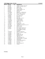
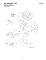
Page 13: ...RepairParts PTS 1 ...
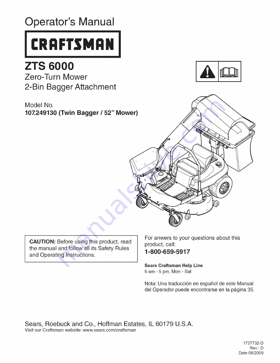
Page 14: ...OTE Unless noted otherwise use the standard hardware torque specification chart Assemble 6 43 57 66 43 34 53 26 49 15 Support Ref Assemble 4 36 39 44 47 52 56 61 63 7 36 47 44 10 52 Mower Housing Assemble 10 14 17 31 32 45 46 55 32 14 PTS 2 ...

Page 15: ...2 48 1927557SM 2 49 1723244SM 1 DESCRIPTION SCREW Truss Head 1 4 20 x 1 2 SCREW Truss Head 1 4 20 x 1 MOUNT Strap PIN Cover Hinge HANDLE CONNECT Tube HNADLE Plastic PIN Latch BRACKET Front Weight Mount BOLT Carriage 1 4 20 x 3 4 CLAMP 1 2 Diameter Rod NUT Conical 25 20 NUT Weld 10 24 PIN Hinge BAG Grass 15 9 X 16 5 RETAINER Spring UPSTOP Deflector HANGER Grass Bag TRIM 31 1 2 HITCH Bagger WASHER 5...

Page 16: ...OTE Unless noted otherwise use the standard hardware torque specification chart Assemble 6 43 57 66 43 34 53 26 49 15 Support Ref Assemble 4 36 39 44 47 52 56 61 63 7 36 47 44 10 52 Mower Housing Assemble 10 14 17 31 32 45 46 55 32 14 PTS 4 ...

Page 17: ...2 1738295YP 1 73 7091627YP 1 DESCRIPTION LATCH SPACER NUT Hex Flange Whiz 3 8 16 NUT Hex Flange 1 4 20 NUT Hex Flange Top Lock 1 4 20 BOLT Carriage 5 16 18 x 3 4 BOLT Carriage 3 8 16 x 7 8 NUT Hex Lock Nylon Insert 10 24 1 4 20 BOLT Carriage 5 16 18 x 1 G5 BOLT Carriage 5 16 18 x 1 1 4 G5 BOLT Carriage 1 4 20 x 5 8 NUT Hex Flange Whiz 1 4 20 SCREW Truss Head Phillips 10 24 x 3 4 STRAP HOOD Black R...

Page 18: ... 4 16 7 8 9 7 8 14 1 8 1 12 19 20 27 31 66 76 11 12 20 23 30 35 50 55 65 75 90 100 160 180 140 155 220 240 in Ibs Nm ft Ibs Nm 2 1 30 3 4 2 3 31 3 5 3 1 43 4 9 3 5 49 5 5 7 6 8 10 9 8 6 10 13 6 15 0 17 23 1 16 3 19 25 8 27 2 30 40 8 31 3 35 47 6 40 8 50 68 0 47 6 55 74 8 68 0 75 102 0 74 8 90 122 4 88 4 110 149 6 102 0 120 163 2 122 4 150 204 0 136 180 244 8 217 6 260 353 6 244 8 300 408 0 190 4 4...

Page 19: ...Briggs Stratton Yard Power Products Group Copyright 2009 Briggs Stratton Corporation Milwaukee Wl USA All Rights Reserved ...

Reviews: