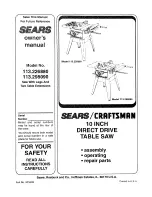
background image

Summary of Contents for 1!3.298090

Page 1: ...y be found at the rear of the base You should record both model and serial number in a safe place for future use JJ YOUR SAFETY _ l Model 113 226880 Model 113 298090 6 CRRFTSMRN 10 INCH DIRECT DRIVE TABLE SAW assembly operating repair parts READ ALL INSTRUCTIONS CAREFULLY J _ Sears Roebuck and Co Hoffman Estates iL 60179 U S A Part No SP 5509 Printed in U S A ...

Page 2: ...rt and Blade Elevation and Bevel Controls See pages 32 34 3 Review and understanding of all safety instructions and operating procedures in this manual 4 Review of the maintenance methods for this saw See page 46 Read the DANGER label found on the front of the saw as shown below WHEN INSTALLING OR MOVING THE SAW lighted 2 To avoid injury from unexpected saw movement A Put the saw on a firm level s...

Page 3: ...thing gloves neckties or jewelry rings wristwatches They can get caught and draw you into moving parts 2 Wear non slip footwear 3 Tie back long hair 5 Roll long sleeves above the elbow Noise levels vary widely To avoid possible hearing damage wear ear plugs or muffs when using saw for long periods of time Any power saw can throw foreign objects into the eyes This can cause permanent eye dam age We...

Page 4: ...ting with the saw watch it while it runs for a short while If it makes an unfamiliar noise or vibrates a lot stop immediately Turn the saw off Unplug the saw Do not restart until finding and fixing the problem 2 Make sure the top of the arbor or cutting tool turns toward the front of the saw 3 Set the cutting tool as low as possible for the cut you re planning 4 KEEP CHILDREN AWAY All visitors sho...

Page 5: ...Switch Key Store it away from children and others not qualified to use the too 4 Unplug the saw glossary of terms for woodworking Anti Kickback Pawls AKP Device which when properly maintained is designed to stop the workpiece from being kicked back at the opera tor during ripping operation Arbor The shaft on which a cutting tool is mounted Crosscut A cuttingor shaping operation made across the wid...

Page 6: ...however require that voltage at motor terminals be not less than the voltage specified on nameplate 3 Most motor troubles may be traced to loose or incor rect connections overloading reduced input voltage which results when small size wires are used inthe supply circuit orwhen the supply circuit is extremely long Always check connection load and supply circuitwhen the motor fails to perform satisf...

Page 7: ...nal Instructions for Cross Cut Type Cuts 5 Glossary 5 Motor Specifications and Electrical Requirements 6 Motor Specifications 6 Motor Safety Protection 6 Connecting to Power Source Outlet 6 General Information 8 Model Description 8 Unpacking and Checking Contents 8 Tools Needed 8 List of Loose Parts Model 113 226880 9 List of Loose Parts Model 113 298090 10 Assembly 12 Assembly of Steel Leg Set 12...

Page 8: ... Screwdriver _ Wrench Hex L 3 16 K_ Wrench Hex L 1 8 Wrenches 3 8 in 7 16 in 1 2 in 9 16 in COMBINATION SQUARE MUST BE TRUE DRAW LIGHT LINE ON BOARD ALONG THIS EDGE 3 i I L_ STRAIGHT EDGE OF BOARD 3 4 THICK THIS EDGE MUST BE PERFECTLY STRAIGHT I SHOULD BE NO GAP OR OVERLAP HERE WHEN SQUARE IS FLIPPED OVER IN DOTTED POSITION Model 113 226880 or 113 298090 is shipped complete in one carton and inclu...

Page 9: ... Nut 1 4 20 2 Bag of Loose Parts 1 Containing the following N Jam Nut 5 16 18 6 Q Lockwasher 5 16 External 6 S Spreader Clamp 1 T Spreader Bracket 1 AA Hex Screw 5 16 18 x 1 6 BB Washer 21 64 x 5 8 x 1 16 6 Bag of Loose Parts 1 Containing the following D Handwheel 2 R Bracket 2 DD Wrench 2 EE Bevel Pointer 1 FF Wire Tie 1 Bag of Loose Parts 1 Containing the following N Hex Jam Nut 5 816 18 6 O Q A...

Page 10: ...me Qty A Miter Gauge 1 B Rip Fence 1 C Blade Guard and Spreader 1 E Rip Fence Guide Bar Rear 1 F Rip Fence Guide Bar with Rip Scale Front 1 H Leg 4 J Side Stiffener 2 K End Stiffener 2 L Table Extension 2 Bag of Loose Parts 1 Containing the following D Handwheel 2 G Wrench 2 B L lO ...

Page 11: ...5 16 18x1 1 2 3 Z Hex Hd Screw 5 16 18x1 1 4 4 Bag of Loose Parts 1 Containing the following W Hex Nut 1 4 20 24 W Hex Jam Nut 3 8 16 8 X Lockwasher 1 4 Extemal Type 24 BB Truss Head Screw 1 4 20xl 2 24 CC Leveling Foot 4 Bag of Loose Parts 2 Containing the following R Flat Washer 17 64x3 4x1 16 4 R Flat Washer 11 32xl 1 16xl 16 8 R Flat Washer 21 64x5 8x1 16 8 W Hex Nut 1 4 20 16 W Hex Jam Nut 5 ...

Page 12: ... remaining Legs and Stiffeners as illustrated 5 Install one 3 8 16 hex nut on each of the Leveling Feet 6 Insert a Leveling Foot throughthe hole inthe bottom of each Leg so the Leveling Foot pad rests on the floor 7 Install another 3 8 16 hex nut on each ofthe Leveling Feet 8 Set leg set upright on floor and securely tighten all nuts 9 After complete assembly you may level the saw by moving the lo...

Page 13: ...ements by adjusting the leveling feet Lock leveling feet into position 7 Securely tighten all leg set screws and nuts SAW BASE HEX HEAD SCREW _ _ FLAT WAS HER _c_ 1 END LOCKWAS E 17 L BOTH MODELS INSTALLING BEVEL POINTER AND HANDWHEELS 1 From among the loose parts find the following hard ware 1 Bevel Pointer 1 Screw 8 32 x 3 8 2 Handwheels 2 Screw Phillips 10 32 x 5 8 2 Lockwasher External 3 16 It...

Page 14: ...OVE and the RIP FENCE must be PARAL LEL to the SAWBLADE WARNING if the sawblade is NOT parallel with the Miter Gauge Groove it is said to have HEEL This condition can cause the workpiece to bind or move away from the Rip Fence at the end of a rip cut possibly causing a kickback I WARNING To avoid injury from accide ntai stall make sure switch is OFF and plug is not con nected to power source outle...

Page 15: ...ustment is made 12 Tighten all screws carefully so as not to move sawblade out of alignment 13 Re check parallelism of marked sawblade tooth to the Miter Gauge Groove Repeat the steps for heeling adjustment if necessary 3 16 IN HEX L WRENCH 113 226880 SHOWN 113 298090 IS SIMILAR BLADE TILT OR SQUARENESS OF BLADE TO TABLE When the Bevel Pointer is pointing directly to the 0 mark on the Bevel Scale ...

Page 16: ...lt blade RIGHT or LEFT checking with your square until blade is square to table D Rotate Stop Collar toward Pivot Nut until it TOUCH ES the Pivot Nut Tighten the setscrews E Check Pointer if it DOES NOT point to the 0 mark onthe bevel scale bend Pointer to read 0 POINTER ADJUSTING SCREW r o Q _ CP_FTgN_N O POSITION _F_ k s il _ l I l 111 _J_ lll _llI _ o 2 2s 30 3_ 40 _ 10 Direct Drive _ HP G _ NG...

Page 17: ...s turn Tilt Handwheel slightly E Install Elevation Handwheel 45 STOP COLLAR TILT SCREW BACK OF SAW BLADE ELEVATION Whenthe Elevation Handwheel isturned CLOCKWISE until it stops the blade must not be more than 2 5 8 inches above the table If the blade extends more than 2 5 8 inches the motor could interfere with the under side of the table causing misalignment With the blade extending 2 5 8 inches ...

Page 18: ...REWS MODEL 113 226880 ONLY ATTACHING AND ASSEMBLING TABLE EXTENSIONS 1 From among the loose parts find the following hard ware Quantity indicated is for 2 extensions 8 Hex Hal Screw 5 16 18 x 1 8 Flat Washer 21 64 x 5 8 x 1 16 8 Lockwasher External 5 16 8 Hex Jam Nut 5 16 18 2 Brackets Items rnarkedwith an asterisk are shown actual size 5 16 18 x 1 HEX HD SCREW 11 32 IN I D FLAT WASH ER 5 16 IN EX...

Page 19: ...inch long screws through a flat washer through the bracket and through the SIXTH hole into the extension Install a Iockwasher and nut on the screw Hand tighten the nut CHECK WITH SQUARE AT 2 PLACES MARKED WITH X REAR OF _ _ _ _ _ _ 7 ih WASHER EXTENS ON_ _ _ __HEX NUT 1 _ _ N _ _ _ OOKWAS E gX D BRACKET 5 16_18 x 1 IN EXTERNAL LOCKWASHER HEX HEAD SC REW 5 16 18 x 1 IN MODEL 113 226880 ONLY INSTALL...

Page 20: ... both bolts 5_ Insert 1 1 2 inch long screw tl_rough external tockwasher flat washer and through the first slot in the Guide Bar Place 1 2 inch long Spacer over screw threads Swing Guide 8at to horizontal position and thread the hex head screw into the hole of the table skirt Finger tighten 6 Insert 1 2 inch long screw through flat washer and the FOURTH slot in the Guide Bar Place 1 2 inch long sp...

Page 21: ...end while engaging front end with Front Guide Bar Lower fence onto tab e_ NOTE It may be necessary to loosen Fence Knob to allow Fence to be installed on Rear Guide Bar Front Guide Bar upwards until fence is ap 10 Move proximately 1 32 inch above tabae Tighten screw at left end of Bar NOTE Fotd a piece of newspaper making 8 thick nesses and place between Rip Fence and table to act as a spacer This...

Page 22: ...n saw upside down on floor NOTE To protect the finished surfaces of the saw and extensions lay a piece of heavy paper or card board on the floor 3 Install Corner Support Brackets Corner Stiffener Brackets 1 4 20 x 1 inch truss head screws 17 64 inch flat washers 1 4 inch external lockwashers and 1 4 20 hex nuts as shown Hand tighten only CORNER STIFFENER 17164 DIA BRACKET FLAT WASHER 1 4 20 tJ_J_ ...

Page 23: ...ws 5 16 18 x 1 1 2 3 Hex Head Screws 5 16 18 x 1 2 Hex Head Screws 5 16 18 x 3 4 8 Hex Jam Nuts 5 16 18 4 Fiat Washers 21 64 x 5 8 x 1 16 3 Spacers 3 4 dia x 1 2 long 10 Lockwashers 5 16 External Items marked with an asterisk are shown actual size 5 16 18 x 3 4 HEX HD SCREW G 5 16 IN EXTERNAL 5 16 iN LOCKWASHERS HEXJAM NUT 5 16 18 X 1 1 2 IN HEX HD SCREW 5 16 18 x 1 IN HEX HD SCREW 21 64 IN WASHER...

Page 24: ... inch ABOVE the edge of the table Securely tighten nuts 7 Install 5 16 18 x 1 1 2 hex head screw through the FOURTH slot in Front Guide Bar that lines up with bracket through the 1 2 inch spacer and the Bracket Install a 5 16 in external iockwasher and 5 16 18 hex jam nut 5 16 18 x 1 1 2 HEX HD 1 7 5 16 IN 8 Remove the three screws from rear of right table extension 9 Attach the Rear Guide Bar ina...

Page 25: ... Set assembly 4 Place one flat washer onto each of the four hex head screws and insert them into each of the mounting holes Be sure the screws go through the saw base holes and the Leg set mounting holes 5 Install a fiat washer Iockwasher and a hex nut on each of the four screws and tighten securely 6 Level the saw to your requirements by adjusting the Leveling Feet Lock Leveling Feet into positio...

Page 26: ...parts find 1 Wire Tie 2 Snap wire tie into 1 4 inch hole in right side of cabinet Route motor cord from inside cabinet through the wire tie Secure cord in wire tie Keep any extra cord on outside of cabinet Do not push extra cord inside cabinet EXTENSION REMOVED FOR PICTURE CLARITY V WIRE TiE BOTH MODELS MOUNTING YOUR SAW TO A WORKBENCH 1 2 To mount the saw on workbench make sure that there isan o_...

Page 27: ...the Fence loosen the Lock Handle and grasp the Fence with one hand at the front For very close adjustments grasp the Guide Bar with both hands and move the Fence with your thumbs b BOTH MODELS SELF ALIGNING SPRING ADJUSTMENT Place Fence on saw but DO NOT LOCK IT Move the REAR END of the Fence slightly to the right of left When you release it the Fence should spring back to its original position If...

Page 28: ...hould be paralle_ to Groove _fi_ is not 1 Loosen the Hex leadscrews 2 Hold Fence head tightly against Bar Move end ot Fence so that tis parallel with Groove 3 Alternately tighten the screws 4 Re check alignment 5 Repeat steps as needed ADJUSTING RiP SCALE iNDiCATOR 1 Turn Elevation Handwheei clockwise untit blade is up as high as it will go BMPORTANT BLADE musl be SQUARE 190 _ to ABLE in order to ...

Page 29: ...t 4 20 SQUARE NUT 1 4 20 WING NUT SPREADER SUPPORT SPREADER BRACKET SPREADER C AMP 17 64 D WASHER 2 Make sure blade is all the way up and square with table 3 Position Spreader Support on Rod until it is even with the end of the Rod WITH TABLE 4 Assemble the 7 8 inch _ong setscrews nuts lockwashers and washers to the Spreader Support Bracket and slip the nuts into the s_otinthe Spreader Support 5 F...

Page 30: ...ROD 1 IMPORTANT To work properly the spreader must always be parallel to the sawblade and adjusted so the cut workpiece will pass on either side of the Spreader without binding or skewing to the side NOTE The Spreader is thinner than the width of the KERF by approximately six thicknesses of paper SPACE EQUAL TO APPROX 3 THICKNESSES OF PAPER KERF WOOD l _ tBLADE _ I I _ s E DE i 1 I SPACE EQUAL TO ...

Page 31: ...EADER BRACKET When replacing the Guard siide the Spreader down and forward between the Spreader Clamp and Spreader Bracket unfit it rests as shown Make sure Wing Nuts are tightened securely this ietsyou remove and replace the Guard without disturbir_ the Spreader alignment f BOTH MODELS ADJUSTING MITER GAUGE MITER GAUGE NOTE Thegraduations are manulacturedto veryctose toIerances which provide suit...

Page 32: ...Insert key into switch B_To turn saw ON stand to either side of the blade never in line with it insert finger under switch lever and pull END of lever out After turning switch ON always allow the blade to come up to full speed before cutting Do not cycle the Motor Switch onand off rapidly as this may cause the sawblade to loosen in the eventthis should ever occur allowthe sawblade to come to a com...

Page 33: ... Extension the facing shoutd be attached to the Fence so that the bottom edge 33 touches the top surface of th e Eixtensios n this case the facing mus_ be shorter titan the Fence This wi_ prevent thin mater al from sliding under the Rip Fence 5 MITER GAUGE head is ocked in t sitior_ tot crosscutting or mitering by t_ghte r_ing the Lock K_ b ALWAYS LOCK _T SECURELY WHEN tN USE Slots are provided in...

Page 34: ...ce insert Place insed into opening in table and push toward rear of saw to engage Spring Clip and until key slot in insert will drop over screw Tighten screw Do not tighten screw to the point where it will deflect the insert EXACT n CUT The yellow Plastic Disc imbedded in the table in front of the sawblade is provided for marking the location of the sawcut on the workpiece A Check Disc If it is ab...

Page 35: ...es should be GLUED to the plywood DO NOT USE NAILS This is to prevent dulling the sawbtade in the event you mistakenly cut into the Push Block Position the handle in the center of the plywood and fasten together with glue and wood screw THESE EDGES MUST BE PARALLEL _4 3 4 _ 3 4 PLYWOOD AUX_L ARY FENCE WORK SUPPORT Make one using a piece of 3 8 inch and 3 4 inch plywood Fasten together with glue an...

Page 36: ...arp blades with property set teeth Consult a I_rofessional blade sharpenerwhen in doubt f Keep blades clean of gum and resin 5 Adjust table inserts flush with the table top NEVER use the saw without the proper insert 6 Make sure all clamps and locks are tight and no parts have any excessive play saw eperations 2 Keep work area clean A CSuttered areas and benches invite accidents Floor must not be ...

Page 37: ...ainst the rotation of the blade NEVER feed material into the cutting tool from the rear of the saw G Always push the workpiece all the way past the sawblade H As much as possible keep your face and body to one side of the sawblade out of line with a possible kickback or throwback I NEVER turn the saw ON before clearing the tabl of all tools wood scraps etc except the wor_ piece and related feed or...

Page 38: ...ccurate square or protractor If necessary the Miter Gauge head can be swiveled slightly to compensate for any inaccuracy NOTE The space between the MiterGauge Bar andthe groove inthe table is held to a minimumduring manufac turing WORKPI ECE 1 I itI l TABLE For maximum accuracy when using the Miter Gauge always favor one side of the groove in the table In other words don t move the Miter Gauge fro...

Page 39: ...amp CAUTION Avoid kickback from twisting the workpiece When clamping the block make sure that the end ot the b_ock is wel_ _nfront of the sawblade Be sure it is clamped securely 5 Slide the workpiece along the Miter Gauge until gt touches the block hold it securely Use Hold Down Clamp _optional accessory for greater accuracy 6 Make the cut pull the workpiece back turn saw off wait for blade to sto...

Page 40: ...he safety instructions on pages 2 3 4 5 36 37 ADDITIONAL SAFETY INSTRUCTIONS 1 NEVER use the Miter Gauge when ripping 2 Use a Push Stick whenever the fence is 2 or more inches from the blade When thru sawing use an auxiliary fence and push block whe never the fence must be between 1 2 and 2 inches of theblade Never thru saw rip cuts less than 1 2 inch wide 3 When using a Push Stick or Push Block t...

Page 41: ... piece of plywood to a sawhorse WORKPIECE TABLE _T ALWAYS SUPPORT LON OR WiDE WORKP ECE_ Keep your hands out of the blade path_ WARNING To avoid kickback use LEFT hand 1 ONLY to guide the workpiece Do not FEED tl_e workpiece with your left hand Stop your left thumb at the front edge of the table Finish the cut with the appropriate pusher Feed the workpiece by pushing forward only on the part of th...

Page 42: ...proximately 1 inch past the front edge of the table Continue to feed using the Push Block Hold the workpiece in position and install the Push Block by sliding it on top of the Auxiliary Fence Work Support this may raise Guard WARNING To avoid injury from blade contact I never thru saw cuts narrower than 1 2 inch wide 1 Narrow strips thicker than the Auxiliary Fence Work Support may enter the Guard...

Page 43: ...ecure and 2 Make sure by trial that the Featherboards will stop a kickback if one should occur RESAWaNG RESAWING is athru sawing cut made by ripping a piece of wood through its thickness Do not attempt to resaw BOWED or WARPED material NOTE To RESAW a piece of wood wider than 3 3 8 inches it will be necessary to remove the blade guard and usethe Auxiliary Fence Work Support See WORK HELPERS Clamp ...

Page 44: ...nown as cutting out a section of the corner of a piece of material across an end or along an edge To make a RABBET requires cuts which do not go all the way through the material Therefore the Blade Guard must be removed RABBET FIRST CUT I I SECOND CUTfJ J 1 Remove Blade Guard 2 For rabbeting along an edge long way of work piece as shown add facing to Rip Fence approxi mately as high as the workpie...

Page 45: ...de loose collar before screwing on the arbor nut Make sure the arbor nut is tight ALWAYS USE DADO INSERT LISTED UNDER REC OMMENDED ACCESSORIES When using the Dado Head it will be necessary to remove the Blade Guard and Spreader USE CAU TION USE MITER GAUGE FENCE FEATHER BOARDS AND PUSH STICKS AS REQUIRED WARNING For your own safety always replace I I the blade Guard and Spreader when you are I I f...

Page 46: ...w dust and wood chips and should be blown out or vacuumed frequently to prevent interference with normal motor ventilation maintenance WARNING To avoid injury from accidental start turn switch OFF and remove plug from power source outlet before maintaining or lubricating your saw Do not allow sawdust to accumulate inside the saw Frequently blow out any dust that may accumulate inside the saw cabin...

Page 47: ... TiLT SCREW PIVOT NUT sears recommends the following accessories ITEM CAT NO Caster Sets 9 22222 or 9 22221 7 In Molding Head Set See Catalog 7 In Molding head See Catalog Moiding iDado Insert for 7 In Dia Molding or Dado Head 9 29933 Work Light See Catalog Sawdust Cotection System 9 29962 7 _n Dia Adjustable Dado Head See Catafog Smaler diameter Molding Heads cannot be used because they do to pro...

Page 48: ...OUBLESHOOTING MOTOR NOTE Motors used on wood working tools are particularly susceptible to the accumulation of sawdust and wood chips and should be blownout or Vacuumed frequently to prevent interference with normal motor ventilation TROUBLE Excessive noise rMotor fails to develop lull power NOTE Low Voltage Power output of motor decreases rapidly with decrease in voltage at motor terminals For ex...

Page 49: ...ge too low to permit motor to reach operating speed 3 Fuses or circuit breakers do not have sufficient capacity Motor overloaded 2 Fuses or circuit breakers do not have sufficient capacity 3 Relay not operating motor does not reach speed REMEDY 1 Request voltage check from the power company 2 Have motor repaired or replaced 3 Have relay replaced 1 2 Feed work s_ower into btade Ctean out sawdust to...

Page 50: ...repair parts 03 LU n n E_ LUeO m_ OCO _ GO f O Zo4 o Iz Z 3 I I 03 m I I I IT 11 II I l 0 50 ...

Page 51: ...Z QI z at I I EQ Z _ Ill 6 m Im O Z i I m o m O Z Q m w vz x c_ _ if _v E E_0_ E 5 o am _ rf3 _j 03 _ r 8 tj x _ x oJ o o _ _ _ _ _ o __ _ _ s LL d _ oo _ _ _ oo_ 0__o o _o coo i_ _i 0 LO r_ 0 0 0 o _ m _o _o _ _o o9 ooo0 _ _ m Oo oo d E Z 51 ...

Page 52: ...repair parts _ U_ ILl g Q l c_ Ij_co a o a_ r T _0 Z_ c oo v co 03_ i _ _ rr n 03 J rr rt CN I 1 4 I I il iI I I 52 ...

Page 53: ...if _ N m d I 6 OJ B _oSg r ca h C d _ X X z z _ gD_ 4m4m 0 6 Z _ _ 0 _ x o o_ _5 _ _ S_ _ oo _ _ _ mm_ o0cc _ z m _ o o mz m _m_ _ L p Od _ _0 _ 0_ _ z 6 mm _m_ o I E _ 0 0 O N v V Z E I m _ N N N _e_ N N_ 8o C 0 _j C j a _ o7 C o_ __2 g 53 ...

Page 54: ...2810 9 62410 10 62519 11 i 62520 12 62974 13 STD551025 14 60208 15 STD581025 DESCRIPTION Guard Saw Pin Bumper Snap In Nut Lock 1 4 20 Link Guard Screw Pan Hd 1 4 20 x 1 1 2 Spacer Link Blade Spreader Pin 1 4 x 1 3 64 Spring Pawl Spacer Pawl Pawl Washer 17164 x 1 2 x 1 32 Nut Push Ring Retaining 1 4 Standard Hardware lem May be purchased locally If this part is removed discard and replace with a ne...

Page 55: ...2 DESCRiPTiON Plug Button Knob Includes Key No 1 Washer 21 64 x 1 2 x 1 32 Indicator Fence Screw Pan Hd Type T 4 40 x 1 4 Head Fence Includes Key No 4 Screw Sems 3 8 16 x t 2 A Channel Fence Channel Fence Screw Pan Hd Type q 8 32 x 1 2 Spring Fence Lock Lock Rear Fence Roller Rear Fence A Rod Fence Lock Rod Fence Lock Spring Head Alignment Includes Key No 17 Lockwasher External No 10 Screw Type A ...

Page 56: ...KEY PART NO NO i 817745 2 STD541231 3 STD551231 4 STD523110 5 STD551031 6 818308 7 62539 8 STD523115 L DESCRIPTION Extension Table 10 x 20 Nut Hex 5 16 18 Lockwasher External 5 16 Screw Hex Head 5 16 18 x 1 Washer 11 32 x 11 16x 1 16 Bracket Spacer Fence Guide Bar Screw Hex Hd 5 16 18 x 1 1 2 Standard Hardware Item May be purchased locally 56 ...

Page 57: ...DESCRIPTION Extension Assembly Complete Screw Serrated Truss Hd 1 4 20 x 1 Bracket Lockwasher External 5 16 Nut Hex 5 16 18 Lockwasher External 1 4 Nut Hex 1 4 20 Extension 10 x 27 Spacer Fence Guide Bar Washer 21 64 x 11 16 x 1 16 Screw Hex Hd 5 16 18 x 1 1 2 Bracket Corner Support No 2 Bracket Corner Stiffener Screw Hex Hd 5 16 18 x 1 1 4 Washer 17 64 x 3 4 x 1 16 Screw Hex Hd 5 16 18 x 1 Standa...

Page 58: ...URE 7 LEG SET KEY NO 1 2 3 PART NO 60314 819441 62554 4 LSTD551225 5 STD541025 6 62553 7 STD541237 8 803835 1 DESCRIPTION Screw Serrated Truss Hd 1 4 20 x 1 2 Leg Stiffener Side Lockwasher Ext 114 Nut Hex 1 4 20 Stiffener End Nut Hex 3 8 16 Foot Leveling 3 8 Standard Hardware Item May be purchased locally 58 ...

Page 59: ... 62383 DESCRIPTION Gauge Assembly Miter Plug Button Knob Includes Key No 1 Washer Plain 21 64 x 1 x 1 16 Gauge Miter Screw Pan Hd 8 32 x 5 16 Lockwasher External No 8 indicator Rod Assembly Miter Gauge includes Key No 9 10 11 Stud Clamp Nut Hex Jam 5 16 18 Stud Pivot 60288 Screw Locking Set 1 4 20 x 3 8 Standard Hardware Item May be purchased locally Stock Item May be secured through the Hardware ...

Page 60: ... 7 days a week t 800 366 PART 1 800 366 7278 For in homemajor brand repair service Call 24 hours a day 7 days a week 1 800 4 RI PAIR 1 800 473 7247 Forthe location of a Sears RepairService Center in your area Call 24 hoursa day 7 days a week t 800 488 1222 llIilI II BiiliB Ill Forinformation on purchasinga Sears Maintenance Agreementor to inquire about an existing Agreement Call 9 am 5 pro Monday ...

Reviews: