Cisco UC500 series, Configuration Manual
The Cisco UC500 series Configuration Manual is a comprehensive guide designed to assist users in setting up their UC500 series devices. This manual is available for free download at manualshive.com, providing step-by-step instructions and valuable insights, ensuring smooth configuration of your Cisco UC500 series product.
Share
Download


Reviews:
No comments
Related manuals for UC500 series
240
Brand: Talkswitch Pages: 20
DVG-2101S
Brand: Abocom Pages: 3
GateKeeper Plus
Brand: Quintum Pages: 1
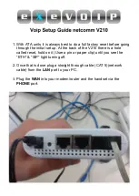
V210
Brand: NetComm Pages: 6
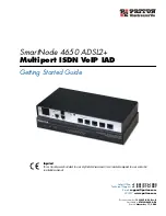
SmartNode 4650 ADSL2+
Brand: Patton Pages: 64
CISCO UC320
Brand: COX Pages: 13
Fonemosa 4204A
Brand: PCI Pages: 18
SmartNode 4830 DSL Series
Brand: Patton Pages: 70
DCM-712
Brand: D-Link Pages: 5
SPA 2102 ATA
Brand: Linksys Pages: 10
LVS 9000
Brand: Linksys Pages: 63

DVG-5004
Brand: D-Link Pages: 73
kx-ns0154la
Brand: Panasonic Pages: 74

Yap Jack Pro
Brand: Net2Phone Pages: 110
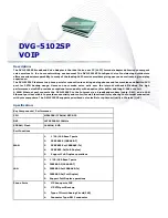
DVG-5102SP
Brand: Abocom Pages: 3
GONU14RS
Brand: XtendLan Pages: 37
VVX 350
Brand: SM Pages: 11
KIRK KWS300
Brand: Polycom Pages: 6


