Cisco TelePresence MX700, Installation Manual
The Cisco TelePresence MX700 is an advanced video conferencing solution designed for immersive collaboration. Ensure seamless installation with our comprehensive Installation Manual, available for free download at [website]. Easily access the manual to set up and optimize your TelePresence MX700, unlocking its full potential for remote communication.
Share
Download


Reviews:
No comments
Related manuals for TelePresence MX700
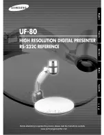
UF-80DX
Brand: Samsung Pages: 10
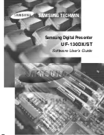
UF-130DX
Brand: Samsung Pages: 33
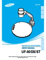
UF-80DX
Brand: Samsung Pages: 46
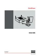
ClickShare
Brand: Barco Pages: 124
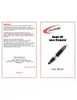
LP2
Brand: Califone Pages: 2
Como
Brand: Hama Pages: 2
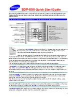
SDP-850
Brand: Samsung Pages: 3
Wireless Multimedia Presenter with Trackball
Brand: Targus Pages: 16
WPM-20R
Brand: Xcellon Pages: 16
VZ-8light4
Brand: WolfVision Pages: 20
AMP32
Brand: Targus Pages: 21
XP350 magic
Brand: x-pointer Pages: 13
i3SYNC FHD RX 4.0
Brand: i3-TECHNOLOGIES Pages: 8
610027
Brand: Equip Pages: 8
i3SIXTY 2
Brand: i3-TECHNOLOGIES Pages: 12
DS1-MP10RX2
Brand: NEC Pages: 204
WIPS1000
Brand: Teq Avit Pages: 16

282350
Brand: Xcellon Pages: 8


