Dual SFP Gigabit QAM Modulator
&LVFR6\VWHPV,QF
678.277.1
5030 Sugarloaf Parkway, Box 465447
Lawrenceville, GA 30042
www.
FLVFR
.com
MAJOR ALARM
MINOR ALARM
CW
GQAM Modulator Model D9479-12 AC DUAL SFP
CW
RF SEL
OPTIONS ENTER
FREQ
LEVEL
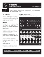
Dual SFP GQAM Front Panel
Use the following diagram to assist you with the installation of the modulator.
Note
: The front panel is identical for both the AC and DC dual SFP GQAM models.
MAJOR ALARM
MINOR ALARM
CW
GQAM Modulator Model D9479-12 AC DUAL SFP
CW
RF SEL
OPTIONS ENTER
FREQ
LEVEL
T12555
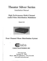
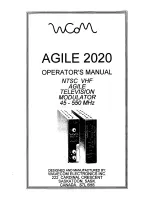
Dual SFP GQAM Back Panels
Use the following diagrams to assist you with the installation of the modulator, as well as the location of the connection ports.
RF OUT 1
CAUTION:
FOR CONTINUED PROTECTION AGAINST FIRE
REPLACE ONLY WITH SAME TYPE 5.0 A SLO BLO 250 V FUSE
RF OUT 2
RF OUT 3
RF OUT 4
ASI IN 1
ASI IN 2
ASI IN 3
ASI IN 4
DA
TA
1
CRAFT
PORT
GND
10/100 BASE T
LINK ACTIVE
DA
TA
2
DA
TA
3
DA
TA
4
FUSE
FUSE
-48 VDC
160w
48 VOLTS DC
T12556
D9479-12 120/230V AC DUAL SFP
D9479-22 48V DC DUAL SFP
POWER 120/130V 60/50Hz 2.5A
RF OUT 1
RF OUT 2
RF OUT 3
RF OUT 4
ASI IN 1
ASI IN 2
ASI IN 3
ASI IN 4
DA
TA
1
CRAFT
PORT
GND
10/100 BASE T
LINK ACTIVE
GIGABIT
ETHERNET
LINK
ACT
LINK
ACT
DA
TA
2
DA
TA
3
DA
TA
4
T4H, 250V
T
-A
-V
BACKUP
MAIN
GIGABIT
ETHERNET
LINK
ACT
LINK
ACT
BACKUP
MAIN
9. Verifying RF Output
To verify that you have established the correct RF output for the RF OUT
port, follow these steps.
a. Connect an RF OUT port on the modulator to a spectrum analyzer.
b. Verify the output level for the frequency and the channel using a
spectrum analyzer.
c. Repeat steps a and b for the remaining RF OUT port connections.
10. Verifying Audio and Video on a DHCT
After sessions are defined on the DNCS, verify that audio and video are
performing properly on a local Digital Home Communications Terminal
(DHCT).
Quick Reference Guide
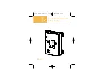
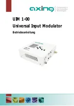
Rack Mount Brackets
Use the following diagram to assist you with the installation of the modulator using the supplied notched rack mount brackets.
CAUTION: Take care to install the notched rack mount brackets as shown in the following picture. Inverting the brackets will block
airflow, which will cause the unit to overheat and damage the unit.
T13737
Cisco
and
the Cisco Systems logo
are registered trademarks or trademarks of Cisco
and/or its af
fi
liates in the U.S. and certain other countries.
Third party
trademarks mentioned are the property of their respective owners.
Product and service availability subject to change without notice.
© 2006-2008
, 2012
Cisco Systems, Inc. All rights reserved.
September 20
12
Pr
inted in
USA
Part Number
78-40
02206
-01
Rev
D