background image

 1

Doc. No.

Copyright © 1994

Cisco Systems, Inc.

All rights reserved.

ciscoBus Token Ring Card and Applique
Installation and Upgrade Instructions

78-0875-04

Product Numbers:
CSC-C2CTR=
APP-LTR2=
MC-C2CTR-V10.2=

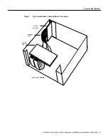
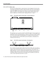
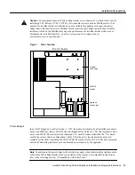
This document contains instructions for installing the multiport ciscoBus Token Ring interface card
(CSC-C2CTR) and Token Ring applique (APP-LTR2) in your AGS+ chassis. This document also
provides instructions for upgrading the C2CTR microcode by replacing a single erasable
programmable read-only memory (EPROM) component on the CSC-C2CTR card. The
CSC-C2CTR provides two or four high-speed Token Ring interfaces for connection to IEEE 802.5
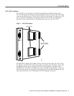
and IBM-compatible Token Ring media at speeds of 4 or 16 Mbps. The APP-LTR2 provides the
interface between the CSC-C2CTR and your Token Ring network. Both the card and applique must
be installed in an AGS+ with a CSC/3 or CSC/4 processor card and a ciscoBus II controller card
(CSC-CCTL2).

The sections in this document include the following:

Product Descriptions, page 2

— CSC-C2CTR Interface Card, page 4

— APP-LTR2 Applique, page 5

Installation Prerequisites, page 6

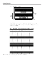
— System Compatibility Requirements, page 6

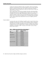
— Ring Speed, page 16

— List of Parts, page 16

— Required Tools, page 17

— Safety, page 17

Preventing Electrostatic Discharge Damage, page 18

Installation, page 18

— Installing the CSC-C2CTR Interface Card, page 19

— Installing the APP-LTR2 Applique, page 20

Summary of Contents for APP-LTR2

Page 1: ...oken Ring interfaces for connection to IEEE 802 5 and IBM compatible Token Ring media at speeds of 4 or 16 Mbps The APP LTR2 provides the interface between the CSC C2CTR and your Token Ring network Both the card and applique must be installed in an AGS with a CSC 3 or CSC 4 processor card and a ciscoBus II controller card CSC CCTL2 The sections in this document include the following Product Descri...

Page 2: ...functional overviews of the CSC C2CTR card and the APP LTR2 applique The CSC C2CTR resides in the AGS system card cage Each port on the CSC C2CTR provides one Token Ring interface and connects to an APP LTR2 applique with an internally routed ribbon cable The APP LTR2 which resides in an applique card cage are installed in the two far right large plate areas in the rear of the AGS The appliques pr...

Page 3: ...n Ring Card and Applique Installation and Upgrade Instructions 3 Product Descriptions Figure 1 Typical Installation Shown Without Card Cages H1467a Interface applique Front of chassis Interface cable Interface card ...

Page 4: ... cable Four green LEDs indicate the status of each port interface When an interface is up or active in the ring the corresponding LED is on The LED is off when the interface is inactive administratively down not internally connected to the applique or the applique is not externally connected to the ring Figure 3 CSC C2CTR ciscoBus Token Ring Card Front Edge View The C2 designator in the product nu...

Page 5: ...ection between the applique and two ports on the CSC C2CTR Figure 4 APP LTR2 Applique The APP LTR2 is installed in an applique card cage mounted on the rear panel of an AGS One or two appliques can be installed in each card cage Because of internal space limitations no more than two applique card cages can be installed in the AGS chassis therefore a maximum of four APP LTR2s can be installed A gro...

Page 6: ...Version 1 2 or later CSC R16M microcode is Version 3 2 or later Refer to the section Compatibility with Other Cards on page 15 for compatibility requirements for all ciscoBus and Multibus cards when running Software Release 9 1 required for CSC C2CTR and CSC CCTL2 operation An applique card cage product number MAS CCG is installed in the chassis and there is at least one empty slot available or Yo...

Page 7: ...Interface 8 TokenRing0 station address 0000 3040 e004 13 buffer RX queue threshold 31 buffer TX queue limit display text omitted Interface 9 TokenRing1 station address 0000 3040 e084 display text omitted Interface 10 TokenRing2 station address 0000 3040 e044 display text omitted Interface 11 TokenRing3 station address 0000 3040 e0c4 display text omitted HSCI 2 controller type 10 0 microcode versio...

Page 8: ...first generation ciscoBus controller card CSC CCTL ciscoBus cards with Microcode Version 10 0 or later are compatible only with the second generation ciscoBus controller card CSC CCTL2 The CSC C2CTR and CSC C2FCIT are compatible only with the CSC CCTL2 The initial release of both cards contained Microcode Version 10 0 Table 1 CSC CCTL2 Interface Card Compatibility Requirements The C2 designator ad...

Page 9: ...ard in ciscoBus slot 0 receives the highest ciscoBus priority while the card in ciscoBus slot 3 receives the lowest ciscoBus priority Slot priorities are set to accommodate the amount of traffic generated by each interface card and the amount of card buffering required Each ciscoBus interface card is placed in a specific slot with regard to other ciscoBus interface cards if any The order of priori...

Page 10: ... MEC Ports Cards C2 HSSI Ports Cards 0 0 0 0 24 4 0 0 0 0 1 1 18 3 0 0 0 0 0 0 18 3 1 1 4 1 0 0 18 3 0 0 0 0 2 2 12 2 0 0 0 0 1 1 12 2 1 1 4 1 1 1 12 2 0 0 0 0 0 0 12 2 2 2 4 1 0 0 12 2 1 1 8 2 0 0 12 2 0 0 6 2 1 1 6 1 0 0 6 2 0 0 6 1 1 1 0 0 3 3 6 1 0 0 0 0 0 0 6 1 3 3 0 0 2 2 6 1 1 1 4 1 2 2 6 1 0 0 4 1 0 0 6 1 2 2 4 1 1 1 6 1 1 1 0 0 1 1 6 1 2 2 Environmental monitor card Processor card Multibu...

Page 11: ... is the only ciscoBus card that needs a card number The card number of the CSC CCTL2 is always 0 which is the factory default no Multibus cards can be set for card number 0 Figure 6 illustrates the correct switch settings for card number 0 all four pins are in the down off position when the CSC CCTL2 is viewed from the front edge of the card viewed as installed in the card cage Figure 6 CSC CCTL2 ...

Page 12: ...he example in Table 3 shows the maximum number of 16 Token Ring interfaces allowable in an AGS without exceeding the power budget also see the section Compatibility with Other Cards on page 15 Chassis Limitations A maximum number of two CSC C2CTRs can be installed in an AGS chassis This limit is due to the internal space available for the APP LTR2s which are installed in an applique card cage Each...

Page 13: ...p View Power Budget In an AGS shipped on or after October 1 1991 the total power drawn by all installed cards must not exceed 300W per chassis In AGS chassis shipped before October 1 1991 the total power must not exceed 260W The earlier chassis contained a 5A circuit breaker rather than the 7 5A circuit used in the current chassis configuration Table 4 lists the power requirements for each card av...

Page 14: ...power requirement of the two new cards If the result is greater than the power requirement for the new cards you can install the new cards without exceeding the power budget The following shows a sample calculation to determine whether two new CSC CTRs can be added to an AGS that already contains several other interface cards All calculations are in watts W 1 Add 4W for each external Ethernet tran...

Page 15: ...nimum required version installed there is no requirement to update the microcode However new microcode versions occasionally fix bugs and provide performance enhancements in addition to implementing new features You will obtain maximum performance and reliability by upgrading to the recommended version Refer to the latest Microcode Release Note publication for current microcode requirements and re...

Page 16: ...as an undefined or incorrect ring speed and is not shut down the ring will beacon which effectively takes the ring down and makes it inoperable List of Parts Verify that you received all of the following parts If any parts are missing contact a customer service representative ciscoBus Token Ring card CSC C2CTR One APP LTR2 for each two CSC C2CTR ports two appliques if you will use all four ports o...

Page 17: ...static discharge Safety Follow these guidelines when working with any electrical equipment Before beginning any procedures requiring access to the chassis interior turn off the system power and disconnect the power cord Never assume that power has been disconnected from a circuit always check Do not work alone when a potentially hazardous condition exists Do not perform any action that creates a p...

Page 18: ...dle printed circuit cards and appliques by the edges only avoid touching the components traces or any connector pins Place a removed card component side up on an antistatic surface or in a static shielding bag If the component will be returned to the factory immediately place it in a static shielding bag Do not remove the wrist or ankle strap until the installation is complete Caution For safety p...

Page 19: ...perly Step 2 On the front access panel shown in Figure 8 turn the two thumbscrews counterclockwise to loosen them do not attempt to remove them from the panel Pull the panel off the chassis and set it aside Step 3 Slip on an ESD wrist or ankle strap and connect it to the chassis as described in the previous section Preventing Electrostatic Discharge Damage Make certain that power to the chassis is...

Page 20: ...is installed in an applique card cage in the rear of the chassis access to the rear of the chassis requires removing the front panel and top cover from the chassis The following describes how to first install the applique in the applique card cage and then install the card cage in the chassis Warning Before removing any cables or fasteners from the chassis turn off the power and unplug the power c...

Page 21: ... card cage and the applique is seated in the card guide See Figure 9 Figure 9 Installing the APP LTR2 in the Applique Card Cage Step 8 If you are installing only one applique replace the filler plate on the left side of the card cage sliding it down so that the edge interlocks with the faceplate of the applique on the right or If you are installing a second APP LTR2 in the card cage install it in ...

Page 22: ...step 2 The large plate area will already be open Step 1 Remove a blank large plate from one of the two far right large plate areas shown in Figure 10 by removing the six screws that secure it Figure 10 Installing the Applique Card Cage in the Chassis Step 2 Label each internal ribbon cable with a Token Ring interface number so that you can connect the applique interfaces to the correct ports on th...

Page 23: ...if your installation requires short or long ground straps Use a short ground strap when you install the applique next to a blank connector plate see Figure 11 or next to an applique that does not contain a hole for the long ground strap screw Use a long ground strap when you install the applique next to an applique that contains a hole for the long ground strap for example another APP LTR2 see Fig...

Page 24: ...with all appliques ground the applique to the chassis to prevent EMI noise on your network interface The applique card cage containing the APP LTR2 s should already be installed in the chassis and secured with at least two screws Refer to Figure 12 while you install the long ground straps Figure 12 APP LTR2 Long Ground Strap Installation Step 1 Remove the Phillips screw from the top center of each...

Page 25: ...he power supply and dangerous voltages are exposed Also the internal airflow is misdirected when the cover is off which can cause the system to overheat and subsequently shut down LED Functions The LEDs on the CSC 3 and CSC 4 processor cards indicate the status of the system software If the system detects a problem at startup the system error LED on the processor card will be on or will flash The ...

Page 26: ...cate that the system software has booted and is operational Figure 14 CSC 3 Processor Card LED Indicators Front Edge View ciscoBus Controller Card LEDs The CSC CCTL2 contains a bank of five LEDs one red LED for each ciscoBus slot and one green OK LED Figure 15 shows the LEDs as viewed with the card installed in the card cage The numbers above each LED indicate the corresponding ciscoBus slot numbe...

Page 27: ...e system power and remove the CSC CCTL2 to check the setting of Switch S1 Ensure that S1 is set for card number 0 which is the factory default See the section Card and Interface Numbering on page 11 If Switch S1 on the CSC CCTL is set to card number 0 and the LEDs still fail to light turn the system power OFF and check switch S1 on each Multibus interface card that was removed from the chassis Ens...

Page 28: ...s are lit turn OFF system power remove the interface card in question install it in a different ciscoBus slot and restart the system If the ciscoBus card still fails to turn on the LED on the CSC CCTL2 refer to the section System Compatibility Requirements on page 6 and ensure that the card type and microcode are compatible with your system Step 7 Check the system console terminal and ensure that ...

Page 29: ...ken Ring interface Note The configure command requires privileged level access to the EXEC command interpreter which usually requires a password Refer to the description that follows and contact your system administrator if necessary to obtain privileged level access Privileged Access to the EXEC Command Interpreter Before you use the configure command you must enter the privileged level of the EX...

Page 30: ... nonvolatile memory Before entering any new interface information you may want to use this command to review the current configuration The following example shows a partial display of the show configuration command output router show config Using 2648 out of 65536 bytes version 9 1 hostname router enable password secretword display text omitted interface TokenRing 0 ip address 131 108 8 35 255 255...

Page 31: ... the requirements for your system configuration Configuration subcommands are described in the Router Products Configuration Guide and Router Products Command Reference publications Refer to the previous example as necessary Caution By default all interfaces are configured as shut down until you enter no shut After you enter no shut or if the interface is already configured as up the interface is ...

Page 32: ...configuration as described in the following section Checking the Configuration After you have configured the ring speed of each interface check the LEDs on the CSC C2CTR and use EXEC command displays to verify the new Token Ring interfaces When the system is started the interface cards query the appliques for interface information If an applique is not connected to its interface card when the syst...

Page 33: ...nformation about the interfaces such as the state of the lines and protocol types use the show interface tokenring EXEC command unit number to display statistics about a specific Token Ring interface The first line of the show interfaces display names the interface and its interface address TR 0 and indicates whether the hardware and line protocol are up or down If the line protocol is down and yo...

Page 34: ...ce Card on page 19 Step 2 Slip on an ESD preventive wrist strap and connect it to the chassis as described in the section Preventing Electrostatic Discharge Damage Make certain that power to the chassis is OFF but that the power cord is fully connected Step 3 Referring to Figure 16 locate the EPROM in socket U98 Note the orientation of the notch the new EPROM must be inserted with the same orienta...

Page 35: ... use your product serial number to activate CIO for a single user during your warranty period Maintenance customers and partners can self register on CIO to obtain additional content and services Available 24 hours a day 7 days a week CIO provides a wealth of standard and value added services to Cisco s customers and business partners CIO services include product information software updates relea...

Page 36: ... with the AGS Hardware Installation and Maintenance publication Access Without Compromise Catalyst CD PAC CiscoFusion CiscoView CiscoWorks HyperSwitch Internetwork Operating System IOS Netscape Point and Click Internetworking SMARTnet SynchroniCD The Packet UniverCD Workgroup Director and Workgroup Stack are trademarks Access by Cisco and Bringing the power of internetworking to everyone are servi...

Reviews: