background image

C H A P T E R

2-1

Cisco 6160 Hardware Installation Guide

OL-2190-02 B0

2

Preparing for Installation

This chapter provides the requirements that are necessary to prepare for the installation of the
Cisco 6160 system.

This chapter contains the following sections:

Safety Requirements, page 2-1

Site Requirements, page 2-10

Required Tools and Equipment, page 2-16

Unpacking the Cisco 6160 System, page 2-18

Verifying Contents, page 2-19

Inspecting for Damage, page 2-19

Caution

Before you begin the installation procedures, read the entire chapter for important information and
safety warnings.

2.1  Safety Requirements

This section describes safety requirements for the Cisco 6160 system. Before you install the
Cisco 6160 system, ensure that all the criteria in this section are met. This section describes the
following safety requirements:

Safety Guidelines, page 2-1

Maintaining Safety with Electricity, page 2-7

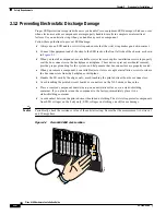
Preventing Electrostatic Discharge Damage, page 2-8

General Maintenance Guidelines, page 2-9

2.1.1  Safety Guidelines

Before working on the equipment, be aware of standard safety guidelines and the hazards that are
involved in working with electrical circuitry to prevent accidents. Adhere to the following cautions and
warnings and those throughout the guide for safe and hazard-free installation.

Summary of Contents for 6160

Page 1: ...rtant information and safety warnings 2 1 Safety Requirements This section describes safety requirements for the Cisco 6160 system Before you install the Cisco 6160 system ensure that all the criteria in this section are met This section describes the following safety requirements Safety Guidelines page 2 1 Maintaining Safety with Electricity page 2 7 Preventing Electrostatic Discharge Damage page...

Page 2: ...equipment Installation and maintenance personnel should be properly grounded by means of grounding straps to eliminate the risk of ESD damage to the equipment Equipment is subject to ESD damage whenever it is removed from the chassis Caution Be careful when you remove the standoff screws and reinsert the screws into the screw holes on the backplane so that the backplane circuitry does not become d...

Page 3: ...des dangers posés par les circuits électriques et familiarisez vous avec les procédures couramment utilisées pour éviter les accidents Pour prendre connaissance des traductions d avertissements figurant dans cette publication consultez le document Regulatory Compliance and Safety Information Conformité aux règlements et consignes de sécurité qui accompagne cet appareil Warnung Dieses Warnsymbol be...

Page 4: ...e lhe poderá causar danos físicos Antes de começar a trabalhar com qualquer equipamento familiarize se com os perigos relacionados com circuitos eléctricos e com quaisquer práticas comuns que possam prevenir possíveis acidentes Para ver as traduções dos avisos que constam desta publicação consulte o documento Regulatory Compliance and Safety Information Informação de Segurança e Disposições Regula...

Page 5: ...be installed and maintained by service personnel only as defined by AS NZS 3260 Clause 1 2 14 3 Service Personnel Warning A readily accessible two poled disconnect device must be incorporated in the fixed wiring Warning To reduce the risk of fire use only No 26 AWG or larger telecommunication line cord Warning Never defeat the ground conductor or operate the equipment in the absence of a suitably ...

Page 6: ...lated telephone wires or terminals unless the telephone line has been disconnected at the network interface Warning Use caution when installing or modifying telephone lines Warning Avoid using a telephone other than a cordless type during an electrical storm There may be a remote risk of electric shock from lightning Warning Do not use a telephone to report a gas leak in the vicinity of the leak W...

Page 7: ... to cool before touching any other part of it or before placing it in an antistatic bag Warning Do not reach into a vacant slot or chassis while you install or remove a module or a fan Exposed circuitry could constitute an energy hazard 2 1 2 Maintaining Safety with Electricity Follow these guidelines when working on equipment that is powered by electricity Locate the emergency power off switch fo...

Page 8: ...dle the I O card by the edges only avoid touching the printed circuit boards or connectors Avoid touching the printed circuit boards or connectors on the NI 2 cards or line cards Place a removed component board side up on an antistatic surface or in a static shielding container If you plan to return the component to the factory immediately place it in a static shielding container Avoid contact bet...

Page 9: ...3 or OC 3c OC 3c NI 2 cards Hot swapping active NI 2 cards interrupts service for the entire system until the NI 2 card is replaced or until a redundant NI 2 takes over system operations However you can hot swap standby NI 2 cards without interrupting service 2 1 4 2 Hot Swapping Blower Trays and PEMs The following sections detail the hot swapping guidelines for the blower tray and power entry mod...

Page 10: ...the slot Do not force the I O card onto the chassis connectors Ensure that the I O card is straight and parallel to the chassis when you install the module onto the connectors The pins on the connectors can be damaged if the I O card is not installed correctly Firmly press on the I O card to ensure that the connectors mate with the chassis correctly 2 2 Site Requirements This section describes req...

Page 11: ...rature of 104 F 40 C 2 2 1 2 Ventilation The following practices ensure proper ventilation for the Cisco 6160 system Chassis placement Leave one rack unit RU under each Cisco 6160 chassis for cabling needs and the intake plenum Blower tray installation A blower tray must be installed in the Cisco 6160 chassis POTS splitter location POTS splitters do not dissipate heat and should be positioned at t...

Page 12: ...ACTIVE STATUS DMT G LITE 4X FLEXI A1 A2 A3 A4 CAP ACTIVE STATUS DMT G LITE 4X FLEXI A1 A2 A3 A4 CAP ACTIVE STATUS DMT G LITE 4X FLEXI A1 A2 A3 A4 CAP ACTIVE STATUS DMT G LITE 4X FLEXI A1 A2 A3 A4 CAP ACTIVE STATUS DMT G LITE 4X FLEXI A1 A2 A3 A4 CAP ACTIVE STATUS DMT G LITE 4X FLEXI A1 A2 A3 A4 CAP ACTIVE STATUS DMT G LITE 4X FLEXI A1 A2 A3 A4 CAP ACTIVE STATUS DMT G LITE 4X FLEXI A1 A2 A3 A4 CAP ...

Page 13: ...nded and that it falls within the internal power supply rating Table 2 2 Rack Space Calculation for Cisco 6160 System Configurations Line Instructions Calculation Cisco 6160 with a POTS Splitter Configuration 1 Total number of Cisco 6160 chassis in the rack Maximum is three chassis per rack include subtending host and subtended node chassis 2 Total number of third party POTS splitters in the rack ...

Page 14: ...ulation 1 If you are using 8xIDSLs multiply 5 5W by the total number of 8xIDSLs installed in the chassis 2 If you are using 8xG SHDSLs multiply 16 5W by the total number of 8xG SHDSLs installed in the chassis 3 If you are using 8xDMTs multiply 24W by the total number of 8xDMTs installed in the chassis 4 If you are using 4xSDSLs multiply 9W by the total number of 4xSDSLs installed in the chassis 5 ...

Page 15: ...ack if it is the only unit in the rack When mounting this unit in a partially filled rack load the rack from the bottom to the top with the heaviest component at the bottom of the rack If the rack is provided with stabilizing devices install the stabilizers before mounting or servicing the unit in the rack We recommend that you mount the Cisco 6160 system in a rack Ensure that vertical hole spacin...

Page 16: ...the following I O cards DS3 2DS3 8xT1 I O card DS3 2DS3 I O card Note The I O card should ship with an EMI cover screws standoff screws and washers PEM s Blower tray Blank faceplates as necessary Third party POTS splitters can be installed in a Cisco 6160 with a POTS splitter configuration Please verify the compatibility with your Cisco representative Telco cables with Champs connectors for the fo...

Page 17: ...35A or equivalent Fiber cable for OC 3c connections SMF or MMF as appropriate 7Console and auxiliary cables Unshielded RJ 45 serial cable that complies with the EIA TIA 232 standard and provides connection to a system console Ethernet connection Cat 5 UTP6 or Cat 5 STP7 cable with an RJ 45 connector that complies with Ethernet standards Necessary equipment for ESD protection Required whenever you ...

Page 18: ...edge and lift with both hands To prevent injury keep your back straight and lift with your legs not your back To unpack the Cisco 6160 system complete the following steps Step 1 Inspect the packing containers If any damage or other signs of mishandling are evident inform both the local freight carrier and Cisco before unpacking Your freight carrier can provide you with the procedures necessary to ...

Page 19: ... 800 553 2447 408 526 7209 tac cisco com 2 6 Inspecting for Damage After you verify that all of the equipment is included carefully examine the assemblies cards and cables for any damage resulting from shipping If you suspect any damage from shipping contact your local freight carrier for procedures on damage claims If you observe any physical defects in the items you ordered obtain standard warra...

Page 20: ...2 20 Cisco 6160 Hardware Installation Guide OL 2190 02 B0 Chapter 2 Preparing for Installation Inspecting for Damage ...

Reviews: