


Installing and Upgrading FRUs
•
Removing and Replacing the Chassis Cover, on page 1
•
Replacing the Power Supply, on page 2
•
Installing Drive Bays, on page 2
•
Upgrading the M.2 Storage Module, on page 3
•
Installing and Removing a DIMM, on page 4
•
Installing and Removing a NIM, on page 7
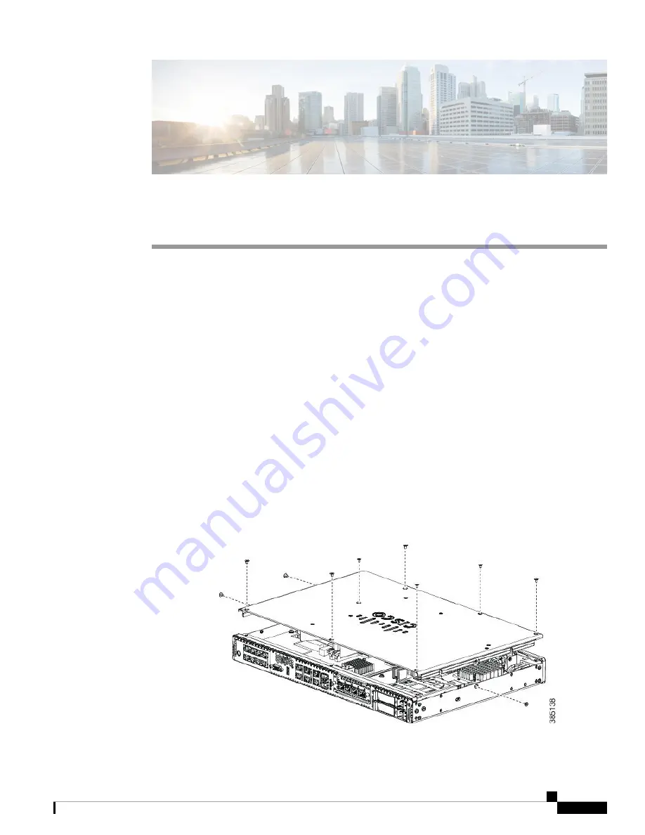
Removing and Replacing the Chassis Cover
These are the steps to remove the chassis cover:
1.
Confirm the router is turned off and disconnected from the power supply or power supplies.
2.
Place the chassis on a flat surface.
3.
Remove the screws at top of the chassis cover.
4.
Remove the screws at the sides of the device (See Figure 11).
5.
Lift the chassis cover once you have removed all the screws.
Figure 1: Removing the Chassis Cover
Installing and Upgrading FRUs
1


