background image


Corporate Headquarters:

Copyright © 2004 Cisco Systems, Inc. All rights reserved.

Cisco Systems, Inc., 170 West Tasman Drive, San Jose, CA 95134-1706 USA

Cisco 1721, 1760, 2621XM, 2651XM, 2691, 3725, 
and 3745 Modular Access Routers and 7206-VXR 
NPE-400 Router FIPS 140-2 Non-Proprietary 
Security Policy

Level 2 Validation
Version 2.4
November 19, 2004

Introduction

This is the non-proprietary Cryptographic Module Security Policy for the Cisco 1721, 1760, 2621XM, 
2651XM, 2691, 3725, 3745, and 7206 VXR NPE-400 routers.  This security policy describes how the 
routers meet the security requirements of FIPS 140-2, and how to operate the routers in a secure FIPS 
140-2 mode.  This policy was prepared as part of the Level 2 FIPS 140-2 certification of the routers.  

FIPS 140-2 (

Federal Information Processing Standards Publication 140-2—Security Requirements for 

Cryptographic Modules

) details the U.S. Government requirements for cryptographic modules.  More 

information about the FIPS 140-2 standard and validation program is available on the NIST website at 

http://csrc.nist.gov/cryptval/

.

This document contains the following sections:

Introduction, page 1

The Cisco 1721, 1760, 2621XM, 2651XM, 2691, 3725, 3745, and 7206 VXR NPE-400 Routers, 
page 3

Secure Operation of the Cisco 1721, 1760, 2621XM, 2651XM, 2691, 3725, 3745, and 7206 VXR 
NPE-400 Routers, page 42

Related Documentation, page 44

Obtaining Documentation, page 45

Documentation Feedback, page 46
Summary of Contents for 2621XM

Page 1: ...erate the routers in a secure FIPS 140 2 mode This policy was prepared as part of the Level 2 FIPS 140 2 certification of the routers FIPS 140 2 Federal Information Processing Standards Publication 140 2 Security Requirements for Cryptographic Modules details the U S Government requirements for cryptographic modules More information about the FIPS 140 2 standard and validation program is available...

Page 2: ...routers ps341 index html For answers to technical or sales related questions please refer to the contacts listed on the Cisco Systems website at www cisco com The NIST Validated Modules website http csrc nist gov cryptval contains contact information for answers to technical or sales related questions for the module Terminology In this document the Cisco 1721 1760 2621XM 2651XM 2691 3725 3745 and ...

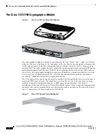
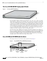
Page 3: ...odules NMs available the modular architecture of the Cisco router easily allows interfaces to be upgraded to accommodate network expansion The Cisco 1721 1760 2621XM 2651XM 2691 3725 3745 and 7206 VXR NPE 400 provide a scalable secure manageable remote access server that meets FIPS 140 2 Level 2 requirements as a multiple chip embedded module This section describes the general features and functio...

Page 4: ...ponents within the case of the device except any installed modular WICs All of the functionality discussed in this document is provided by components within this cryptographic boundary The 1760 requires that a special opacity shield be installed over the right hand side air vents in order to operate in FIPS approved mode The shield decreases the effective size of the vent holes reducing visibility...

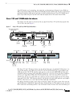
Page 5: ...iliary port supporting 115Kbps Dial On Demand Routing ideal for back up WAN connectivity A WIC is inserted into one of the WIC slots which are located on the back panel of the 1721 and the front panel of the 1760 WICs interface directly with the processor and cannot perform cryptographic functions they only serve as a data input and data output physical interface The physical interfaces include a ...

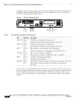
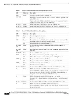
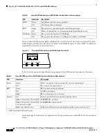
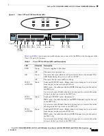
Page 6: ...fic information for each installed interface Table 1 Cisco 1721 Rear Panel LEDs and Descriptions LED Indication Description WIC 0 OK Green A WIC is correctly inserted in the card slot Off No WIC present WIC incorrectly inserted in the card slot WIC 1 OK Green A WIC is correctly inserted in the card slot Off No WIC present WIC incorrectly inserted in the card slot FDX Green The interface is transmi...

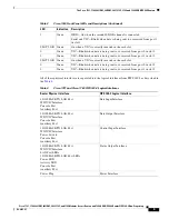
Page 7: ...ot powered on OK Green The router has successfully booted up and the software is functional This LED blinks during the power on self test POST Off The router has not successfully booted up WIC 0 ACT CH0 Green Serial and DSU CSU cards Blinks when data is being sent to or received from the port on the card in the WIC0 slot ISDN cards On solid when the first ISDN B channel is up for the card in the W...

Page 8: ... 1 OK Green n when a packet voice data module PVDM is correctly inserted in PVDM card slot 1 MOD OK Green On when a VPN module is present FDX Green The interface is transmitting data in full duplex mode Off When off the interface is transmitting data in half duplex mode 100 Mbps Green The speed of the interface is 100 Mbps Off The speed of the interface is 10 Mbps or no link is established LINK Gr...

Page 9: ... SLOT 3 OK Green On when a VIC is correctly inserted in the card slot 0 Green VIC Blinks when data is being sent to or received from port 0 in slot 3 1 Green VIC Blinks when data is being sent to or received from port 1 in slot 3 Table 3 Cisco 1760 Front Panel LEDs and Descriptions Continued LED Indication Description Table 4 Cisco 1721 and Cisco 1760 FIPS 140 2 Logical Interfaces Router Physical ...

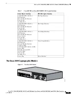
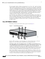
Page 10: ...the functionality discussed in this document is provided by components within this cryptographic boundary Cisco IOS features such as tunneling data encryption and termination of Remote Access WANs via IPSec Layer 2 Forwarding L2F and Layer 2 Tunneling Protocols L2TP make the Cisco 2600 an ideal platform for building virtual private networks or outsourced dial solutions Cisco 2600 s RISC based proc...

Page 11: ... any cryptographic functions WICs are similar to Network Modules in that they greatly increase the router s flexibility A WIC is inserted into one of two slots which are located above the fixed LAN ports WICs interface directly with the processor They do not interface with the cryptographic card therefore no security parameters will pass through them WICs cannot perform cryptographic functions the...

Page 12: ... LED Indication Description LINK Green An Ethernet link has been established Off No Ethernet link established FDX Green The interface is transmitting data in full duplex mode Off When off the interface is transmitting data in half duplex mode 100 Mbps Green The speed of the interface is 100 Mbps Off The speed of the interface is 10 Mbps or no link is established POWER RPS ACTIVITY 99496 Table 6 Ci...

Page 13: ...100BASE TX LAN Port WIC Interface Network Module Interface Console Port Auxiliary Port Data Output Interface 10 100BASE TX LAN Port WIC Interface Network Module Interface Power Switch Console Port Auxiliary Port Control Input Interface 10 100BASE TX LAN Port WIC Interface Network Module Interface LAN Port LEDs 10 100BASE TX LAN Port LEDs Power LED Redundant Power LED Activity LED Console Port Auxi...

Page 14: ...to 70 thousand packets per second Kpps throughput capacity Cisco 2691 Module Interfaces The interfaces for the router are located on the rear panel as shown in Figure 11 Figure 11 Cisco 2691 Physical Interfaces The Cisco 2691 router features console and auxiliary ports dual fixed LAN interfaces a Network Module slot two Cisco WAN interface card WIC slots and a Compact Flash slot LAN support includ...

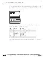
Page 15: ...auxiliary port for remote system access or dial backup using a modem The 10 100Base T LAN ports have Link Activity 10 100Mbps and half full duplex LEDs Figure 12 shows the LEDs located on the rear panel with descriptions detailed in Table 8 Figure 12 Cisco 2691 Rear Panel LEDs Table 8 Cisco 2691 Rear Panel LEDs and Descriptions LED Indication Description LINK On An Ethernet link has been establish...

Page 16: ...ttached and operational and overall activity link status Figure 13 Cisco 2691 Front Panel LEDs Table 9 provides more detailed information conveyed by the LEDs on the front panel of the router All of these physical interfaces are separated into the logical interfaces from FIPS 140 2 as described in Table 10 SYS RPS PWR ACT 99502 Table 9 Cisco 2691 Front Panel LEDs and Descriptions LED Indication De...

Page 17: ...ce Network Module Interface Console Port Auxiliary Port Compact Flash slot Data Input Interface 10 100BASE TX LAN Port WIC Interface Network Module Interface Console Port Auxiliary Port Compact Flash slot Data Output Interface 10 100BASE TX LAN Port WIC Interface Network Module Interface Power Switch Console Port Auxiliary Port Control Input Interface 10 100BASE TX LAN Port WIC Interface Network M...

Page 18: ...and Layer 2 Tunneling Protocols L2TP make the Cisco 3700 an ideal platform for building virtual private networks or outsourced dial solutions Cisco 3700 s RISC based processor provides the power needed for the dynamic requirements of the remote branch office achieving wire speed Ethernet to Ethernet routing with up to 100 thousand packets per second Kpps throughput capacity for the 3725 and 225 Kp...

Page 19: ...5Kbps Dial On Demand Routing ideal for back up WAN connectivity 1 Interface Card Slots 5 FastEthernet 0 1 2 Network Modules 6 Compact Flash Slot 3 Power Supply 7 Auxiliary Port 4 FastEthernet 0 0 8 Console Port SEE MANUAL BEFORE INSTALLATION AL CD LP RD TD SEE MANUAL BEFORE INSTALLATION DSU 56K AL CD LP RD TD SEE MANUAL BEFORE INSTALLATION DSU 56K EN V0 BANK 4 BANK 3 BANK 2 BANK 1 BANK 0 NM HDV VW...

Page 20: ...panel for a console terminal for local system access and an auxiliary port for remote system access or dial backup using a modem The 10 100Base T LAN ports have Link Activity 10 100Mbps and half full duplex LEDs Figure 16 shows the LEDs located on the rear panel with descriptions detailed in Table 11 and Table 12 Figure 16 Cisco 3725 and Cisco 3745 Rear Panel LEDs SEE MANUAL BEFORE INSTALLATION AL...

Page 21: ...green Operating voltages on mainboard are within acceptable ranges Off Error condition is detected in the operating ranges SYS Solid green Router operating normally Blinking green Router running ROM monitor no errors detected Amber Router receiving power but malfunctioning Off Router not receiving power CF Solid or blinking green Do not eject Compact Flash CF device is busy Off CF can be ejected d...

Page 22: ...s SYS LED ACT LED SYS PS1 LED 48V PS1 LED 48 PS2 LED SYS PS2 LED PWR LED SYS RPS LED ACT LED PWR SYS RPS ACT 99507 Table 13 Cisco 3725 Front Panel LEDs and Descriptions LED Indication Description PWR Solid green Router is receiving power Off Router is not receiving power SYS RPS Solid green System is operating normally Rapid blinking System is booting up or in ROM monitor mode Blinking once per se...

Page 23: ...f Power supply not present or failed 48V PS1 and 48V PS2 Solid green 48V power module installed and operating normally Amber 48V power module installed and powered off or fault condition occurred Off 48V power module not present or failed Table 14 Cisco 3745 Front Panel LEDs and Descriptions Continued LED Indication Description Table 15 Cisco 3725 and Cisco 3745 FIPS 140 2 Logical Interfaces Route...

Page 24: ...connection apparatus between the port adapter and the motherboard daughterboard that hosts the port adapter but the boundary does not include the port adapter itself In other words the cryptographic boundary encompasses all hardware components within the case of the device except any installed modular port adapters All of the functionality discussed in this document is provided by components withi...

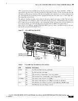
Page 25: ...ing redundant power Cisco 7206 VXR NPE 400 Module Interfaces The interfaces for the router are located on the front panel Input Output I O Controller with the exception of the power switch and power plug The module has two Fast Ethernet 10 100 RJ 45 connectors for data transfers in and out The module also has two other RJ 45 connectors for a console terminal for local system access and an auxiliar...

Page 26: ...ntroller is functional or enabled This LED goes on during a successful router boot and remains on during normal operation of the router IO POWER OK Amber Indicates that the I O controller is on and receiving DC power from the router midplane This LED comes on during a successful router boot and remains on during normal operation of the router Off Powered off or failed Slot 0 Slot 1 Green These LED...

Page 27: ... Once the Crypto Officer has configured the encryption and decryption functionality the User can use this functionality after authentication to the User role by providing a valid User username and password The Crypto Officer can also use the encryption and decryption functionality after authentication to the Crypto Officer role The module supports RADIUS and TACACS for authentication and they are ...

Page 28: ...as protocol ID addresses ports TCP connection establishment or packet direction Status Functions view the router configuration routing tables active sessions use Gets to view SNMP MIB II statistics health temperature memory status voltage packet statistics review accounting logs and view physical interface status Manage the router log off users shutdown or reload the outer manually back up router ...

Page 29: ...e the enclosure will leave tamper evidence Step 3 Place the second label on the router as shown in Figure 20 The tamper evidence label should be placed so that the one half of the tamper evidence label covers the top half of the left side of the enclosure and the other half covers the bottom half of the left side of the router Any attempt to remove the enclosure will leave tamper evidence Step 4 P...

Page 30: ... labels completely cure within five minutes Figure 20 Cisco 1721 and Cisco 1760 Tamper Evidence Label Placement To apply serialized tamper evidence labels to the Cisco 2621XM and Cisco 2651XM Step 1 Clean the cover of any grease dirt or oil before applying the tamper evidence labels Alcohol based cleaning pads are recommended for this purpose The temperature of the router should be above 10 C Step...

Page 31: ...cond label on the router as shown in Figure 22 The tamper evidence label should be placed so that the one half of the tamper evidence label covers the enclosure and the other half covers the left side of the router Any attempt to remove the enclosure will leave tamper evidence Step 4 Place the third label on the router as shown in Figure 22 The tamper evidence label should be placed so that the on...

Page 32: ...overs the left side of the router Any attempt to remove the enclosure will leave tamper evidence Step 4 Place the third label on the router as shown in Figure 23 The tamper evidence label should be placed so that the one half of the label covers the enclosure and the other half covers the top double sized Network Module slot Any attempt to remove a network module will leave tamper evidence Step 5 ...

Page 33: ...t to remove a network module will leave tamper evidence Step 5 Place the fourth label on the router as shown in Figure 23 The tamper evidence label should be placed so that the half of the label covers the enclosure and the other half covers the bottom left Network Module slot Any attempt to remove a network module will leave tamper evidence Step 6 Place the fifth label on the router as shown in F...

Page 34: ...ep 7 Place the sixth label on the router as shown in Figure 24 The tamper evidence label should be placed so that one half of the label covers the enclosure and the other half covers the port adapter slot 4 Step 8 Place the seventh label on the router as shown in Figure 24 The tamper evidence label should be placed so that one half of the label covers the enclosure and the other half covers the po...

Page 35: ...s have non repeated serial numbers they may be inspected for damage and compared against the applied serial numbers to verify that the module has not been tampered Tamper evidence seals can also be inspected for signs of tampering which include the following curled corners bubbling crinkling rips tears and slices The word OPEN may appear if the label was peeled back 61228 ETHERNET 10BT EN AB LE D ...

Page 36: ...er the generation of 400 bites hence it is zeroized periodically Also the operator can turn off the router to zeroize this key DRAM plaintext 2 CSP 2 The private exponent used in Diffie Hellman DH exchange Zeroized after DH shared secret has been generated DRAM plaintext 3 CSP 3 The shared secret within IKE exchange Zeroized when IKE session is terminated DRAM plaintext 4 CSP 4 Same as above DRAM ...

Page 37: ... label command invalidate the DNS server s public key and it frees the public key label which in essence prevent use of that key This label is different from the label in the above key This key does not need to be zeroized because it is a public key NVRAM plaintext 18 CSP 18 The SSL session key Zeroized when the SSL connection is terminated DRAM plaintext 19 CSP 19 The ARAP key that is hardcoded i...

Page 38: ...his password is zeroized by overwriting it with a new password NVRAM plaintext 29 CSP 29 The ciphertext password of the CO role However the algorithm used to encrypt this password is not FIPS approved Therefore this password is considered plaintext for FIPS purposes This password is zeroized by overwriting it with a new password NVRAM plaintext 30 CSP 30 The RADIUS shared secret This shared secret...

Page 39: ... CSP 6 r r w d CSP 7 r r w d CSP 8 r r w d CSP 9 r r w d CSP 10 r r w d CSP 11 r r w d CSP 12 r r w d CSP 13 r r w d CSP 14 r r w d Table 19 Role and Service Access to CSPs Continued SRDI Role Service Access Policy Role Service User Role Status Functions Network Functions Terminal Functions Directory Services Crypto Officer Role Configure the Router Define Rules and Filters Status Functions Manage...

Page 40: ...P 18 r r w d CSP 19 r r w d CSP 20 r r w d CSP 21 r w d r w d CSP 22 r r w d CSP 23 r r w d CSP 24 r d r w CSP 25 r r w d CSP 26 r r w d Table 19 Role and Service Access to CSPs Continued SRDI Role Service Access Policy Role Service User Role Status Functions Network Functions Terminal Functions Directory Services Crypto Officer Role Configure the Router Define Rules and Filters Status Functions M...

Page 41: ...ctronically The pre shared keys are used with Diffie Hellman key agreement technique to derive DES 3DES or AES keys The pre shared key is also used to derive HMAC SHA 1 key Internet Key Exchange with RSA signature authentication All pre shared keys are associated with the CO role that created the keys and the CO role is protected by a password Therefore the CO password is associated with all the p...

Page 42: ...itions into an error state Within the error state all secure data transmission is halted and the router outputs status information indicating the failure Self tests performed by the IOS image Power up tests Firmware integrity test RSA signature KAT both signature and verification DES KAT TDES KAT AES KAT SHA 1 KAT PRNG KAT Power up bypass test Diffie Hellman self test HMAC SHA 1 KAT Conditional te...

Page 43: ...sole to the ROM monitor and automatically boots the Cisco IOS image From the configure terminal command line the Crypto Officer enters the following syntax For Cisco 7200 series routers enter config register 0x0102 For Cisco 1700 2600 and 3700 series routers enter config register 0x0101 The Crypto Officer must create the enable password for the Crypto Officer role The password must be at least 8 c...

Page 44: ...llowed via a secure IPSec tunnel between the remote system and the module The Crypto officer must configure the module so that any remote connections via telnet are secured through IPSec SSH access to the module is only allowed if SSH is configured to use a FIPS approved algorithm The Crypto officer must configure the module so that SSH uses only FIPS approved algorithms Related Documentation For ...

Page 45: ...t Cisco documentation on the World Wide Web at this URL http www cisco com univercd home home htm You can access the Cisco website at this URL http www cisco com International Cisco websites can be accessed from this URL http www cisco com public countries_languages shtml Ordering Documentation You can find instructions for ordering documentation at this URL http www cisco com univercd cc td doc e...

Page 46: ...d resolving technical issues with Cisco products and technologies The Cisco TAC website is available 24 hours a day 365 days a year The Cisco TAC website is located at this URL http www cisco com tac Accessing all the tools on the Cisco TAC website requires a Cisco com user ID and password If you have a valid service contract but do not have a login ID or password register at this URL http tools c...

Page 47: ...rity 4 P4 You require information or assistance with Cisco product capabilities installation or configuration There is little or no effect on your business operations Obtaining Additional Publications and Information Information about Cisco products technologies and network solutions is available from various online and printed sources Cisco Marketplace provides a variety of Cisco books reference ...

Page 48: ...xecutives You can access iQ Magazine at this URL http www cisco com go iqmagazine Internet Protocol Journal is a quarterly journal published by Cisco Systems for engineering professionals involved in designing developing and operating public and private internets and intranets You can access the Internet Protocol Journal at this URL http www cisco com ipj Training Cisco offers world class networki...

Reviews: