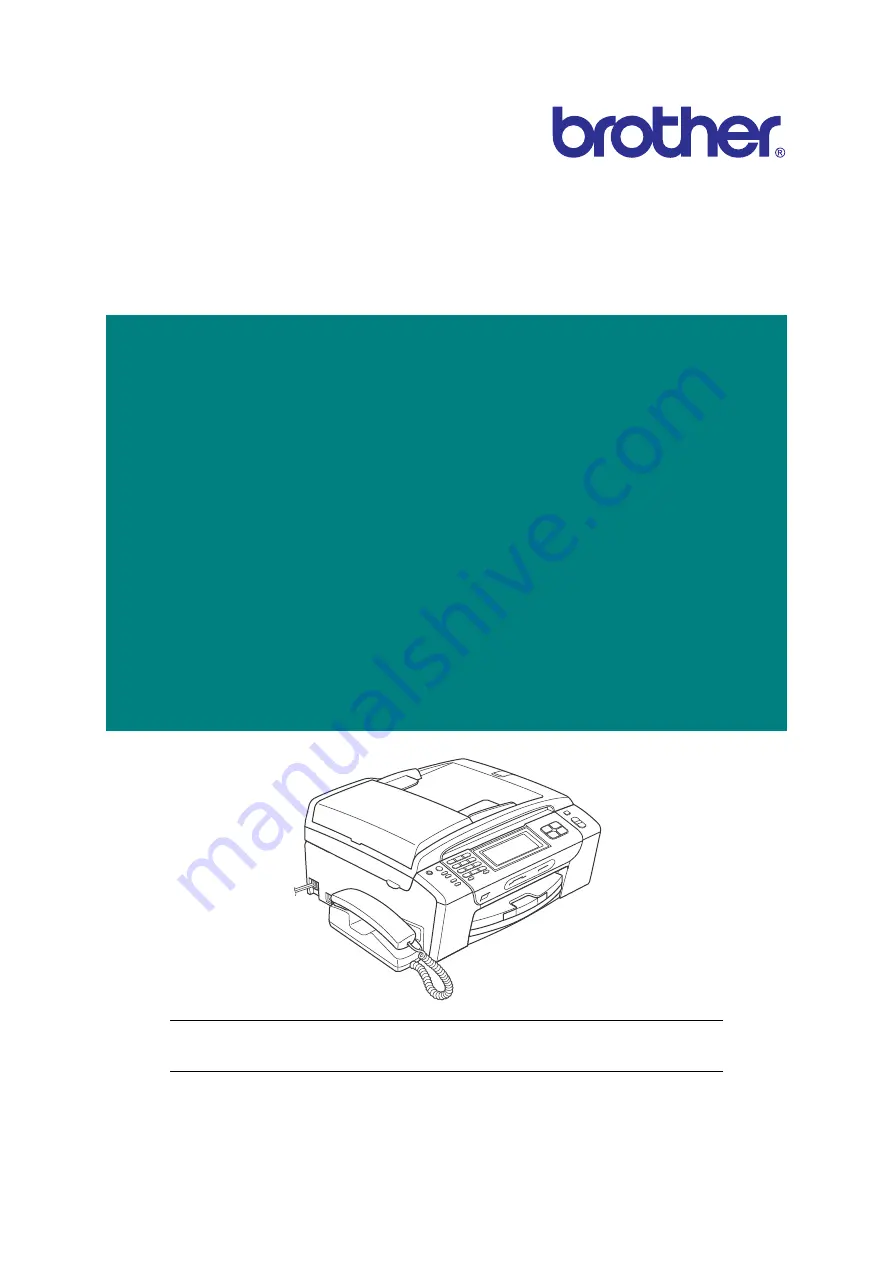
Summary of Contents for MFC-J220

Page 1: ...N MFC495CW 795CW DCPJ125 J315W DCPJ515W J715W MFCJ220 J265W J270W MFCJ410 J410W J415W MFCJ615W J630W DCPJ140W March 2010 SM FAX112 4 8CAJ 8CAK 8CAP Read this manual thoroughly before maintenance work Keep this manual in a convenient place for quick and easy reference at all times ...

Page 2: ...nternational Business Machines Corporation CompactFlash is a registered trademark of SanDisk Corporation Memory Stick is a registered trademark of Sony Corporation SanDisk is a licensee of the SD and miniSD trademarks xD Picture Card is a trademark of Fujifilm Co Ltd Toshiba Corporation and Olympus Optical Co Ltd PictBridge is a trademark Memory Stick Pro Memory Stick Pro Duo Memory Stick Duo and ...

Page 3: ...le below shows the functional comparison between the models covered by this manual Model DCP375CW DCP395CN MFC255CW MFC295CN MFC495CW MFC795CW RAM 32 MB 40 MB 32 MB 40 MB 48 MB LCD Monochrome LCD 16 charas x 1 line 3 3 inch wide color Monochrome LCD 16 charas x 1 line 3 3 inch wide color 5 0 inch wide color Touch panel Wired LAN Wireless LAN WLAN PCB Handset Hook switch and its PCB Speaker Backup ...

Page 4: ...ending upon each destination Model MFCJ220 MFCJ265W MFCJ270W MFCJ410 MFCJ410W MFCJ415W MFCJ615W MFCJ630W RAM 32 MB 40 MB LCD 1 9 inch STN color LCD 3 3 inch TFT color LCD Touch panel Wired LAN Wireless LAN WLAN PCB Handset Hook switch and its PCB Speaker Backup battery TAD Microphone PhotoCapture Center PictBridge USB flash memory drive ADF Photo tray FAX ...

Page 5: ...leshooting procedures This will help service personnel pinpoint and repair defective components CHAPTER 5 HANDLING DATA HELD IN THE MACHINE PRIOR TO REPAIR Describes how to handle data held in the machine to be repaired At the user site if the machine cannot print FAX data received and left in the machine due to the printing mechanism defective the service personnel should instruct the end user to...

Page 6: ...endix 1 Reading Labels Shows the location of labels put on some parts and describes the coding information for serial number and head property data Appendix 2 Firmware Installation Provides instructions on how to change firmware stored in the flash ROM on the main PCB or load firmware to a new main PCB from the host PC Appendix 3 EEPROM Customizing Codes Provides instructions on how to set up the ...

Page 7: ...pendix 6 Circuit Diagrams Provides the circuit diagrams of the MJ PCB and power supply PCB Appendix 7 Deletion of User Setting Information Provides instructions on how to delete user setting info recorded in the machine ...

Page 8: ...vi Confidential SAFETY PRECAUTIONS Symbols used in the documentation ...

Page 9: ...vii Confidential ...

Page 10: ...viii Confidential ...

Page 11: ...ix Confidential ...

Page 12: ...x Confidential ...

Page 13: ...xi Confidential ...

Page 14: ...xii Confidential ...

Page 15: ...xiii Confidential ...

Page 16: ...Confidential CHAPTER 1 PARTS NAMES AND FUNCTIONS ...

Page 17: ...s and names of components and describes their functions Information about the keys on the control panel is included to help you check operation or make adjustments CONTENTS 1 1 OUTLINE 1 1 1 2 CONTROL PANEL 1 3 1 3 COMBINATIONS OF TWO KEYS FOR SPECIAL FUNCTIONS 1 18 1 4 COMPONENTS 1 19 ...

Page 18: ... For MFC only 3 For models with handset 4 Media slots for 10 Scanner cover Scanner unit 1 ADF document cover ASSY For models with ADF 2 Control panel 3 Ink cartridge cover 7 Telephone line jack 2 5 Paper tray 6 Port for PictBridge 8 External telephone line jack 2 PhotoCapture Center USB flash memory drive 1 frontview Document cover For models without ADF 9 Handset 3 ...

Page 19: ...ges 4 Media slots for PhotoCapture Center 1 Insert a memory card here 5 Paper tray Load paper here Paper will be fed into the machine sheet by sheet 6 Port for PictBridge USB flash memory drive 2 Connect a digital camera with PictBridge to this connector using the USB cable Insert a USB flash memory drive here 7 Telephone line jack 3 Plug in the modular plug on the telephone line here 8 External t...

Page 20: ...1 3 Confidential 1 2 CONTROL PANEL DCP375CW ...

Page 21: ...1 4 Confidential ...

Page 22: ...1 5 Confidential DCP395CN ...

Page 23: ...1 6 Confidential ...

Page 24: ...1 7 Confidential MFC255CW 295CN ...

Page 25: ...1 8 Confidential ...

Page 26: ...1 9 Confidential MFC495CW ...

Page 27: ...1 10 Confidential ...

Page 28: ...1 11 Confidential MFC795CW ...

Page 29: ...1 12 Confidential ...

Page 30: ...1 13 Confidential DCPJ125 J315W J515W J715W 8 7 6 5 1 2 4 3 ...

Page 31: ...1 14 Confidential ...

Page 32: ...1 15 Confidential MFCJ220 J265W J270W J410 J410W J415W J615W J630W 6 7 8 5 2 4 3 1 ...

Page 33: ...1 16 Confidential Mono Start Colour Start ...

Page 34: ...1 17 Confidential DCPJ140W 6 7 8 5 2 4 3 1 ...

Page 35: ...tion of keys on the control panel Special functions Combination of keys Available for Displaying the firmware version Models with numerical keypad on the control panel Stop Exit Models without numerical keypad on the control panel Alternative to the Menu key on the touch panel Scan Copy Models with touch panel This function is useful when the touch panel is inoperable ...

Page 36: ...ngine unit PF encoder registration sensor harness unit Flushing box Hook switch PCB Handset Handset mount Front cover Lower cover Power supply PCB MJ PS shield unit Paper tray ASSY Paper tray ASSY Ink absorber box Main PCB ASSY Ink refill ASSY Maintenance unit Ink cartridge cover Inner media module cover WLAN PCB COMPONENTS_BHmini9e MJ PCB For models without ADF For models with ADF For models with...

Page 37: ...Confidential CHAPTER 2 SPECIFICATIONS ...

Page 38: ... 4 Memory 2 6 2 1 5 Security 2 7 2 1 6 Interface 2 7 2 1 7 Others 2 8 2 2 TELEPHONE 2 11 2 2 1 Quick Auto Dials 2 12 2 2 2 Tel Service 2 13 2 2 3 Message Center 2 14 2 3 FAX 2 15 2 3 1 Sending 2 17 2 3 2 Receiving 2 18 2 3 3 PC FAX 2 19 2 4 PRINTER 2 20 2 5 COPY 2 22 2 6 SCANNER 2 25 2 7 PHOTO CAPTURE 2 27 2 7 1 PictBridge 2 31 2 8 SOFTWARE 2 33 2 9 NETWORK 2 34 2 9 1 Wired 2 35 2 9 2 Wireless 2 3...

Page 39: ...Confidential 2 12 PAPER 2 42 2 12 1 Paper Specifications 2 42 2 12 2 Printable Area 2 44 ...

Page 40: ...ope only N A FAX COPY Print demo U S A only FAX COPY Print LCD demo U S A only FAX COPY LCD demo Europe only LCD Demo N A Yes U S A Europe only N A N A Yes U S A Europe only Test Print Print Quality Alignment Check Sheet by pressing the Ink key For models with touch panel use the Ink key on the touch panel Model DCPJ125 DCPJ315W DCPJ515W DCPJ715W DCPJ140W Technology Inkjet Print Head 94 nozzles li...

Page 41: ... Sheet Model DCP375CW DCP395CN MFC255CW MFC295CN MFC495CW MFC795CW Media Sizes Standard Tray A4 LTR LGL EXE B5 JIS A5 A6 Photo 102 x 152 mm 4 x 6 inches Indexcard 127 x 203 mm 5 x 8 inches Photo 2L 127 x 178 mm 5 x 7 inches Post Card 1 100 x 148 mm 3 9 x 5 8 inches Post Card 2 Double 148 x 200 mm 5 8 x 7 9 inches C5 Envelope Com 10 DL Envelope Monarch JE4 Envelope Photo Tray N A Photo 102 x 152 mm...

Page 42: ...inches Post Card 1 100 x 148 mm 3 9 x 5 8 inches Post Card 2 Double 148 x 200 mm 5 8 x 7 9 inches C5 Envelope Com 10 DL Envelope Monarch JE4 Envelope Photo Tray N A Photo 102 x 152 mm 4 x 6 inches Photo L 89 x 127 mm 3 5 x 5 inches N A Lower Tray N A Duplex N A ADF width length N A 148 148 mm to 215 9 355 6 mm 5 8 5 8 inches to 8 5 14 0 inches N A Scanner Glass width length Up to 215 9 297 mm up t...

Page 43: ... 89 x 127 mm 3 5 x 5 inches Lower Tray N A Duplex N A ADF width length N A 148 148 mm to 215 9 355 6 mm 5 8 5 8 inches to 8 5 14 0 inches Scanner Glass width length Up to 215 9 297 mm up to 8 5 11 7 inches Media Weights Standard Tray 64 220 g m2 17 58 lb Photo Tray N A 64 220 g m2 17 58 lb Lower Tray N A Duplex N A ADF N A 64 90 g mm2 17 24 lb Media Types Standard Tray Plain Inkjet Glossy cast res...

Page 44: ...270W MFCJ410 MFCJ410W J415W MFCJ615W J630W Paper Input sheets Standard Tray 100 80 g m2 Photo Tray N A 20 thickness 0 25 mm Lower Tray N A ADF N A 15 90 g m2 Output Paper Capacity sheets 50 80 g m2 Model DCP375CW DCP395CN MFC255CW MFC295CN MFC495CW MFC795CW LCD Type Size 16 x 1 line 3 3 inch Wide Color LCD 16 x 1 line 3 3 inch Wide Color LCD 5 0 inch Wide Color LCD Touch Screen N A Yes Backlight C...

Page 45: ...5CN MFC255CW MFC295CN MFC495CW MFC795CW Memory Capacity physical megabytes 32 MB 40 MB 32 MB 40 MB 48 MB Memory Backup with battery 24 hours N A Yes For TAD messages or fax preview only Backup Print ON OFF in function menu N A Yes Model DCPJ125 DCPJ315W DCPJ515W DCPJ715W DCPJ140W Memory Capacity physical megabytes 32 MB 40 MB 32 MB Memory Backup with battery 24 hours N A Backup Print ON OFF in fun...

Page 46: ...ock Yes Secure Function Lock N A Model DCP375CW DCP395CN MFC255CW MFC295CN MFC495CW MFC795CW Host Interface USB 2 0 Hi Speed LAN Yes N A Yes Wireless LAN Yes N A Yes N A Yes PictBridge N A Yes N A Yes USB Flash Memory N A Yes N A Yes Acceptable Media Card Memory Stick Memory Stick Pro Secure Digital Secure Digital High Capacity xD Picture Card xD Picture Card TypeM TypeM TypeH Memory Stick Memory ...

Page 47: ... Secure Digital Secure Digital High Capacity Model DCP375CW DCP395CN MFC255CW MFC295CN MFC495CW MFC795CW On Off Switch Yes Power Source U S A 100 120 VAC 50 60 Hz Europe Asia Oceania 220 240 VAC 50 60 Hz Operating Environment Temperature Best Print Quality 10 35 20 33 degrees centigrade Power Consumption Average Copying Standby Sleep OFF mode U S A 21 5 3 0 45 W 24 6 3 0 45 W 23 5 3 0 7 W 26 6 3 5...

Page 48: ... Hz Europe 220 240 VAC 50 60 Hz Asia Oceania 220 VAC 50 60 Hz except TWN model 100 120 VAC 50 60 Hz TWN model Operating Environment Temperature Best Print Quality 10 35 20 33 degrees centigrade Power Consumption Average Copying Standby Sleep OFF mode U S A 18 5 3 5 1 5 0 45 W N A 18 5 3 5 1 5 0 45 W Europe Asia Oceania 17 3 5 1 5 0 45 W 17 3 5 2 0 45 W 17 3 5 2 0 5 W 17 6 3 5 0 5 W 17 3 5 1 5 0 45...

Page 49: ...3 degrees centigrade Power Consumption Average Copying Standby Sleep OFF mode U S A 19 4 2 5 0 65 W 19 6 5 3 5 0 5 W Europe Asia Oceania 19 5 4 5 2 5 0 65 W 19 5 4 2 5 0 65 W 19 5 4 5 2 5 0 65 W 19 5 6 3 5 0 5 W Machine Noise Operating 50 dBA Maximum Machine Dimensions W x D x H 390 x 368 x 150 mm 390 x 375 x 180 mm Machine Weight U S A 6 8 kg 15 0 lb 6 9 kg 15 2 lb N A 7 8 kg 17 2 lb 8 0 kg 17 6 ...

Page 50: ...PE API support N A Duplex Speaker Phone Key N A Yes PBX Feature Europe Only N A Yes Hold Mute N A Yes Music on Hold N A Monitoring the Line on Hold with Music N A Model MFCJ220 MFCJ265W J270W MFCJ410 MFCJ410W J415W MFCJ615W J630W Handset N A Digital Cordless Phone N A Battery Charger for Digital Cordless Phone N A Outside Telephone N A SKYPE API support N A Duplex Speaker Phone Key N A PBX Feature...

Page 51: ...40 100 x 2 numbers Figures of One Touch Speed Dial N A 20 digits Registerable Number Of Characters N A 16 characters Group Dial Up to X groups N A Yes 6 Telephone Index Search Speed dial key N A Yes Model MFCJ220 MFCJ265W J270W MFCJ410 MFCJ410W J415W MFCJ615W J630W One Touch Dial N A Speed Dial 40 100 x 2 numbers Figures of One Touch Speed Dial 20 digits Registerable Number Of Characters 16 charac...

Page 52: ...all List Indication N A Yes External TAD Interface N A Yes Distinctive Ringing U S A N A Yes Europe N A Yes Denmark United Kingdom only Asia Oceania N A Yes Australia New Zealand Singapore Hong Kong only Model MFCJ220 MFCJ265W J270W MFCJ410 MFCJ410W J415W MFCJ615W J630W Caller ID Yes Call Waiting Caller ID N A Call from Caller ID List Yes Call from Call List Yes Call waiting Ready N A Backup Calle...

Page 53: ...CJ220 J265W J270W J410 J410W J415W J615W J630W Not available Model DCP375CW DCP395CN MFC255CW MFC295CN MFC495CW MFC795CW TAD N A Yes ICM Recording Time N A Maximum 29 minutes or Maximum 99 messages Maximum 180 seconds message Toll Saver N A Yes Recording Conversation N A Yes with beep OGM User Recording Time MC TAD F T N A 20 seconds ...

Page 54: ...with ADF Document Scanning Width N A LTR FB 208 mm A4 FB 204 mm LTR FB 208 mm A4 FB 204 mm LTR LGL ADF 208 mm A4 ADF 208 mm Color FAX Document Send Receive N A Yes Yes ITU T color FAX Memory Send Receive N A No No ITU T color FAX Display FAX Send N A Yes Receive N A Yes Super Fine N A Yes TX RX B W only Gray Scale Color Fax N A Mono 64 Color 256 Contrast Auto S Light S Dark N A Yes Dual Access N A...

Page 55: ... LTR A4 LGL with ADF Document Scanning Width LTR FB 208 mm A4 FB 204 mm LTR FB 208 mm A4 FB 204 mm LTR LGL ADF 208 mm A4 ADF 208 mm Color FAX Document Send Receive Yes Yes ITU T color FAX Memory Send Receive No No ITU T color FAX Display FAX Send N A Receive N A Super Fine Yes TX RX B W only Gray Scale Color Fax Mono 64 Color 256 Contrast Auto S Light S Dark Yes Dual Access Yes B W only Enhanced R...

Page 56: ...to 400 pages Brother Chart MMR N A Up to 200 pages Up to 480 pages Broadcasting Speed One Touch Manual N A Yes 40 50 locations Yes 100 x 2 numbers 50 locations Fax Forwarding N A Yes B W only Model MFCJ220 MFCJ265W J270W MFCJ410 MFCJ410W J415W MFCJ615W J630W Delayed Timer up to 50 B W only N A Up to 50 B W only Polled Sending type B W only U S A N A Yes Standard Europe Asia Oceania N A Yes Standar...

Page 57: ... Standard Sequential Secure Timer Auto Reduction N A Yes Out of Paper Reception ITU T Test Chart 1 MMR N A Up to 170 pages Up to 400 pages Brother Chart MMR N A Up to 200 pages Up to 480 pages Model MFCJ220 MFCJ265W J270W MFCJ410 MFCJ410W J415W MFCJ615W J630W Easy Receive Fax Detect Yes Fax detect only Polling Receiving type B W only U S A N A Yes Standard Sequential Europe Asia Oceania N A Yes St...

Page 58: ... N A Mono Sending N A Yes Network USB Receiving N A Yes Network USB N A for MAC PC Fax Protocol N A TX PC FAX Driver RX Class 2 TX PC FAX Driver Broadcasting N A Up to 50 Model MFCJ220 MFCJ265W J270W MFCJ410 MFCJ410W J415W MFCJ615W J630W Color Mono Mono Sending Yes USB only Yes Network USB Yes USB only Yes Network USB Receiving N A Yes Network USB N A for MAC PC Fax Protocol TX PC FAX Driver RX Cl...

Page 59: ...Yes Ink Save Mode Firm PC N A Yes Yes N A Yes Yes Model DCPJ125 DCPJ315W DCPJ515W DCPJ715W DCPJ140W Print Speed A4 LTR time calculated including paper feeding Up to 33 27 ppm Mono 450 x 150 dpi Color 600 x 150 dpi Up to 35 28 ppm Mono 450 x 150 dpi Color 600 x 150 dpi Up to 33 27 ppm Mono 450 x 150 dpi Color 600 x 150 dpi Resolution horizontal x vertical Up to 1200 x 6000 dpi Auto Duplex Print N A...

Page 60: ...n horizontal x vertical Up to 1200 x 6000 dpi Auto Duplex Print N A Manual Duplex Print Yes Print Paper Margin upper lower left right Borderless printing On 0 0 0 0 mm 0 0 0 0 inch Off 3 3 3 3 mm 0 12 0 12 0 12 0 12 inches Borderless for A4 LTR A6 Photo 102 x 152 mm 4 x 6 inches Index card 127 x 203 mm 5 x 8 inches Photo 2L 127 x 178 mm 5 x 7 inches Post Card 1 100 x 148 mm 3 9 x 5 8 inches only 1...

Page 61: ...izontal x vertical Mono Print Maximum 1200 x 1200 dpi Scan Maximum 1200 x 1200 dpi Color Print Maximum 600 x 1200 dpi Scan Maximum 600 x 1200 dpi Multi Copy Stack Yes 99 Sort N A Yes Mono Only Yes Reduction Enlargement 25 400 in 1 increments N in 1 2 in 1 4 in 1 A4 LTR only Mono only 2 in 1 4 in 1 A4 LTR only Mono Color 2 in 1 4 in 1 A4 LTR only Mono only 2 in 1 4 in 1 A4 LTR only Mono Color Poste...

Page 62: ...pm Mono Color Resolution horizontal x vertical Mono Print Maximum 1200 x 1200 dpi Scan Maximum 1200 x 1200 dpi Color Print Maximum 600 x 1200 dpi Scan Maximum 600 x 1200 dpi Multi Copy Stack Yes 99 Sort N A Yes N A Reduction Enlargement 25 400 in 1 increments N in 1 2 in 1 4 in 1 A4 LTR Executive only Mono Color Poster Yes 3 x 3 Auto Skew Adjustment N A Fit to Page Yes Copy Enhancement Book Copy S...

Page 63: ...esolution horizontal x vertical Mono Print Maximum 1200 x 1200 dpi Scan Maximum 1200 x 1200 dpi Color Print Maximum 600 x 1200 dpi Scan Maximum 600 x 1200 dpi Multi Copy Stack Yes 99 Sort N A Yes Yes Reduction Enlargement 25 400 in 1 increments N in 1 2 in 1 4 in 1 A4 LTR Executive only Mono Color Poster Yes 3 x 3 Auto Skew Adjustment N A Fit to Page Yes Copy Enhancement Book Copy Shadow Correctio...

Page 64: ...to Image Yes OCR Yes E mail Yes File Yes Media Media Card or USB Flash Memory Yes Scan to Media Card only Yes Yes Card only USB Flash Memory is N A Yes Scan to Media Card only FTP N A E mail Server N A Document Scanning Width Length 210 mm Color Depth Input 36 bits Output 24 bits Model DCPJ125 DCPJ315W DCPJ515W DCPJ715W DCPJ140W Auto Crop Firm PC N A Yes Yes N A Mono Color Color Scanner Color Scan...

Page 65: ...270W MFCJ410 MFCJ410W J415W MFCJ615W J630W Auto Crop Firm PC N A Yes Yes Mono Color Color Scanner Color Scan Speed Mono Color 100 dpi Maximum 3 24 4 55 seconds LTR Maximum 3 44 4 83 seconds A4 Resolution horizontal x vertical Optical 1200 x 2400 dpi Interpolated 1200 x 1200 dpi For XP Vista Windows 7 up to 19200 x 19200 dpi with Scanner Utility Gray Scale Color Scanner 256 Scan to Image Yes OCR Ye...

Page 66: ... Inkjet Glossy Photo Tray N A Plain Inkjet Glossy N A Plain Inkjet Glossy Lower Tray N A Print Paper Margin upper lower left right PCC Borderless printing On 0 0 0 0 mm 0 0 0 0 inches Off 3 3 3 3 mm 0 12 0 12 0 12 0 12 inches Available Paper Size for Full Maximum Size Printing All sizes N A All sizes Direct Print Size for A4 LTR N A for A3 LGR B4 8 x 10 cm 3 x 4 inches 9 x 13 cm 3 5 x 5 inches 10 ...

Page 67: ...ye Skin Tone Scenery Auto correct Model DCPJ125 DCPJ315W DCPJ515W DCPJ715W DCPJ140W Acceptable Media Type Size Media Cards Memory Stick 16 128 MB Memory Stick Pro 256 MB 16 GB MagicGate Yes if not use MG function N A Secure Digital 16 MB 2 GB MiniSD with Adapter Secure Digital High Capacity 4 16 GB N A USB Flash Memory N A Up to 32 GB N A Paper Sizes Standard Tray LTR A4 10 x 15 cm 4 x 6 inches 13...

Page 68: ...Card USB Flash Memory N A Monochrome Sepia N A Yes N A Trimming N A Yes N A Search from Date N A Yes N A Slide show N A Yes N A Photo Enhance N A Yes Remove red eye Skin Tone Scenery Auto correct N A Model MFCJ220 MFCJ265W J270W MFCJ410 MFCJ410W J415W MFCJ615W J630W Acceptable Media Type Size Media Cards Memory Stick 16 128 MB Memory Stick Pro 256 MB 16 GB MagicGate Yes if not use MG function Memo...

Page 69: ...opping Full Auto Yes Yes Media Format DPOF Ver 1 0 Ver 1 1 Exif DCF Up to Ver 2 1 Image Format Print by Media Card USB Flash Memory Photo Print JPEG N A Photo Print JPEG avi mov JPEG avi mov Color Enhancement PCC Yes Removable Disk Media Card USB Flash Memory Yes read write Card only USB Flash Memory is N A Yes read write both Card USB Flash Memory Scan to Media Media Media Card or USB Flash Memor...

Page 70: ...m Size only N A Maximum Size only Borderless Cropping Full Auto N A Yes No N A Yes No Index Print N A DPOF N A Yes N A Yes Color Enhancement N A Yes N A Yes Print Quality N A Normal Fine Printer Setting N A Normal Fine Printer Setting Model DCPJ125 DCPJ315W DCPJ515W DCPJ715W DCPJ140W Paper Size N A A4 LTR 4 x 6 inches Printer Setting N A Paper Type N A Plain Paper Inkjet Paper Glossy Printer Setti...

Page 71: ...MFCJ615W J630W Paper Size N A A4 LTR 4 x 6 inches Printer Setting Paper Type N A Plain Paper Inkjet Paper Glossy Printer Setting Direct Print Size for A4 LTR N A Maximum Size only Borderless Cropping Full Auto N A Yes No Index Print N A DPOF N A Yes Color Enhancement N A Yes Print Quality N A Normal Fine Printer Setting ...

Page 72: ...nal 1 Windows XP Home Windows XP Professional Windows XP Professional x64 Edition Windows Vista Windows 7 Windows Server 2003 print only via network Windows Server 2003 x64 Edition print only via network Windows Server 2003 R2 print only via network Windows Server 2003 R2 x64 Edition print only via network Windows Server 2008 print only via network Windows Server 2008 R2 print only via network Mac...

Page 73: ...6 N A LDAP N A FAX to E mail N A RSS reader N A Model DCPJ125 DCPJ315W DCPJ515W DCPJ715W DCPJ140W Printer N A Yes Scanner N A Yes PC FAX N A Internet FAX Firmware N A Format Scan to E mail server N A Protocols IPv4 N A ARP RARP BOOTP DHCP APIPA Auto IP WINS NetBIOS name resolution DNS Resolver mDNS LLMNR responder LPR LPD Custom Raw Port Port9100 FTP Server SNMPv1 TFTP server ICMP Web Service Prin...

Page 74: ...BOOTP DHCP APIPA Auto IP WINS NetBIOS name resolution DNS Resolver mDNS LLMNR responder LPR LPD Custom Raw Port Port9100 FTP Server SNMPv1 TFTP server ICMP Web Service Print LLTD responder Protocols IPv6 N A LDAP N A FAX to E mail N A RSS reader N A Model DCP375CW DCP395CN MFC255CW MFC295CN MFC495CW MFC795CW Model name Ethernet Embedded NC 190h N A Embedded NC 190h Network connection Ethernet Ethe...

Page 75: ...EAP WiFi Certification WiFi B and G N A WiFi B and G N A WiFi B and G Setup Support Utility Secure EZ Setup Yes N A Yes N A Yes AOSS WLAN model only Yes N A Yes N A Yes WPS WiFi Protected Setup Yes N A Yes N A Yes Auto Switch WLAN WIRED LAN N A Mobile Print N A Model DCPJ125 DCPJ315W DCPJ515W DCPJ715W DCPJ140W Model Name Wireless N A Embedded NC 220w Embedded NC 270w Network Connection Wireless N ...

Page 76: ...less N A IEEE 802 11b g N A IEEE 802 11b g Wireless Security N A SSID 32 chr WEP 64 128 bits WPA PSK TKIP AES WPA2 PSK AES NO LEAP N A SSID 32 chr WEP 64 128 bits WPA PSK TKIP AES WPA2 PSK AES NO LEAP WiFi Certification N A WiFi B and G N A WiFi B and G Setup Support Utility Secure EZ Setup N A AOSS WLAN model only N A Yes N A Yes WPS WiFi Protected Setup N A Yes N A Yes Auto Switch WLAN WIRED LAN...

Page 77: ...rtridges U S A Approx 300 240 pages Approx 300 240 pages Europe Asia Oceania Approx 280 210 pages Approx 300 240 pages Approx 280 210 pages Approx 300 240 pages Supply Standard Cartridges U S A Approx 450 325 pages Approx 450 325 pages Europe Asia Oceania N A Approx 450 325 pages N A Approx 450 325 pages SupplyLow Yield Cartridges U S A N A Europe Asia Oceania Approx 300 260 pages N A Approx 300 2...

Page 78: ...urope Asia Oceania Approx 280 210 pages Approx 300 240 pages Approx 280 210 pages Supply Standard Cartridges U S A Approx 450 325 pages N A Approx 450 325 pages Europe Asia Oceania N A Approx 450 325 pages N A SupplyLow Yield Cartridges U S A N A Europe Asia Oceania Approx 300 260 pages N A Approx 300 260 pages Supply High Yield Cartridges U S A N A Europe Asia Oceania N A Brother Paper for Plain ...

Page 79: ...nia Approx 280 210 pages Approx 300 240 pages Supply Standard Cartridges U S A Approx 450 325 pages N A Approx 450 325 pages Europe Asia Oceania N A Approx 450 325 pages SupplyLow Yield Cartridges U S A N A Europe Asia Oceania Approx 300 260 pages N A Supply High Yield Cartridges U S A N A Europe Asia Oceania N A Brother Paper for Plain Glossy and Inkjet U S A Plain LTR Inkjet LTR Glossy resin coa...

Page 80: ...To Be Repaired 30 minutes Model DCPJ125 DCPJ315W DCPJ515W DCPJ715W DCPJ140W Recommended monthly print volume 50 to 1000 pages 250 to 800 pages Monthly Volume 2500 pages Machine Life 30000 pages or 5 years MTBF Mean Time Between Failures 4000 hours MTTR Mean Time To Be Repaired 30 minutes Model MFCJ220 MFCJ265W J270W MFCJ410 MFCJ410W J415W MFCJ615W J630W Recommended monthly print volume 50 to 1000 ...

Page 81: ... 127 x 203 mm 5 x 8 inches Yes Post Card 1 100 x 148 mm 3 9 x 5 8 inches Yes Post Card 2 Double 148 x 200 mm 5 8 x 7 9 inches Yes Envelopes C5 Envelope 162 x 229 mm 6 4 x 9 inches Yes DL Envelope 110 x 220 mm 4 3 x 8 7 inches Yes COM 10 105 x 241 mm 4 1 8 x 9 1 2 inches Yes Monarch 98 x 191 mm 3 7 8 x 7 1 2 inches Yes JE4 Envelope 105 x 235 mm 4 1 x 9 3 inches Yes Transparencies Letter 215 9 x 279...

Page 82: ... may cause decreased output quality Transparencies designed for laser printers copiers may stain your next document Use only transparencies recommended for inkjet printing You can only print on both sides of the paper with PC printing using Windows Paper Type Item Paper Type Item Letter Plain BP60PL100 USA only A4 Plain BP60PA Letter Glossy Photo BP71GLTR BP61GLL USA only A4 Glossy Photo BP71GA4 L...

Page 83: ...tial 2 12 2 Printable Area Top 1 Bottom 2 Left 3 Right 4 Cut Sheet 3 mm 0 12 inches 3 mm 0 12 inches 3 mm 0 12 inches 3 mm 0 12 inches Envelopes 12 mm 0 47 inches 24 mm 0 95 inches 3 mm 0 12 inches 3 mm 0 12 inches ...

Page 84: ...Confidential CHAPTER 3 THEORY OF OPERATION ...

Page 85: ...0 1 Overview 3 10 2 Features 3 11 3 Head carriage unit 3 12 4 Ink cartridges 3 17 5 Ink refill assembly 3 19 6 Ink supply tubes 3 20 3 2 2 2 Head maintenance mechanism 3 21 1 Overview 3 21 2 Maintenance unit components 3 22 3 Mechanisms constituting the head maintenance mechanism 3 24 4 Power transmission route to the head maintenance mechanism and motor rotational direction 3 29 5 Purge types ink...

Page 86: ...ction MFC Scanner Control Section DCP Printer Control Section Print data AC Color LCD Touch panel USB interface WLAN PCB PhotoCapture Center Paper feeding mechanism Power supply Ink jet printer unit Head carriage unit Carriage PCB with head flat cables Carriage motor Ink refill ASSY Maintenance unit Host Compact Flash Memory Stick SD Memory Card xD Picture Card Paper feed motor ASF motor LAN inter...

Page 87: ... encoder ASF encoder and CR encoder various sensors and two thermistors Scanner Mechanism Printing Mechanism Ink supply and ink jet mechanism head maintenance mechanism and carriage drive mechanism Right Left ADF_Scanner_1_BHmini9 Document path for ADF scanning Document for flat bed scanning Front Rear Carriage drive mechanism Ink supply and ink jet mechanism Head maintenance mechanism 3_01_BHmini...

Page 88: ...3 3 Confidential Paper pulling in registration feeding and ejecting mechanisms Recording paper path Front Rear 3_02_BHmini9 Recording paper path in the paper tray ...

Page 89: ...e mechanism See Section 3 2 2 3 Carriage motor DC motor Paper pulling in registration feeding and ejecting mechanisms See Section 3 2 2 4 ASF motor 2 DC motor Paper feed motor DC motor Encoders See Section 3 2 3 Paper feed motor encoder PF encoder ASF motor encoder ASF encoder Carriage motor encoder CR encoder Sensors See Section 3 2 3 Document front sensor 1 Document rear sensor 1 Scanner cover s...

Page 90: ...n the next page shows the components making up the ADF document pull in roller document separation roller document feed rollers ADF motor and document front and rear sensors For further details on the sensors see Section 3 2 3 For models with ADF Document cover ADF unit ADF document cover ASSY Scanner top cover CIS drive belt CIS flat cable Scanner base CIS idle pulley CIS rail 3_03 CIS drive asse...

Page 91: ...ADF offer only flat bed scanning ADF_Scanner_2_BHmini9 ADF pull in piece ADF motor Document front sensor actuator Separation pad Document feed roller 1 Document ejection pinch rollers Document rear sensor actuator Document feed roller 2 Left Pinch rollers 2 CIS unit Pinch rollers 1 Document separation roller Document pull in roller Right Document cover Ejected document support section Document gui...

Page 92: ...uides The machine ejects subsequent pages under this one to preserve the document page order 2 Flat bed scanning CIS unit moves under stationary document The user lifts the document cover places a page or open book face down on the glass plate and closes the document cover The CIS drive mechanism details below operates for each scanning command executed The CIS unit first moves to the white refere...

Page 93: ... collects air bubbles that result from pressure changes on the ink To keep the optimum head performance the head maintenance mechanism shown on page 3 31 uses the rotational torque of the ASF motor to cap the head nozzles in order to prevent them from drying up It also uses the rotational torque of the paper feed motor to purge for removing air bubbles from the head carriage unit and wipe off any ...

Page 94: ...f the maintenance unit Clutch gears L and R shown on page 3 37 Clutch gear L switches the transmission route of the ASF motor rotation between the paper pulling in mechanism and the head capping carriage lock mechanisms Clutch gear R transmits the rotational torque of the paper feed motor to the purge gear for purge air removing and head wiper mechanisms ASF rotary encoder This generates a signal ...

Page 95: ...ge unit below The four ink cartridges black yellow cyan and magenta are mounted on the ink refill assembly For further details see 4 Ink cartridges below The ink refill assembly secures the ink cartridges and connects them to the corresponding ink supply tubes For further details see 5 Ink refill assembly below The ink supply tubes supply the head carriage unit with ink fed from the ink cartridges...

Page 96: ...maintenance unit to suck both air and ink through the ink supply tubes Leaving too long interval between this priming and actual use however risks air bubbles increased viscosity and other quality issues with the ink in the supply tubes Before using this machine for the first time therefore this machine automatically replaces the ink supply path contents with fresh ink using an initial purge a rep...

Page 97: ...owever because of the nature of piezoelectric materials fluctuation in manufacturing accuracy and other factors The front end therefore leaves the production line with head property labels giving property data The manufacturer writes this property data to the EEPROM on the main PCB incorporating this unit Based on the property data of the front end the processor drives piezoelectric ceramic actuat...

Page 98: ...ves foreign materials from the ink Metal plates These form the head nozzle pressure chambers ink flow paths and manifolds Nozzle plate This plate has a total of 376 nozzles 47 nozzles x 2 lines staggered x 4 rows black yellow cyan and magenta Head driver This flexible circuit board holds the piezoelectric driver chip Nozzle array head bottom plate viewed from the top Nozzle Magenta Cyan Paper feed...

Page 99: ...perpendicular to that surface Drive signals removing this voltage for specific channel electrodes allow the piezoelectric elements to return to their original shape sucking ink into the corresponding channels Reapplying the bias voltage stretches the elements once again applying pressure to the ink spraying it from the head nozzle The ink drop hits the paper on the platen forming a dot Pressure ch...

Page 100: ... or lowering the pressure in the right chamber Air vent unit At regular scheduled intervals this vents any air bubbles that have accumulated in the damper assemblies The air vent rods in the maintenance unit push up the shut off valves opening the air vent flow paths Damper ASSY Yellow Shut off valves Air vent unit Air vent cap Damper ASSY Cyan Damper ASSY Black Damper ASSY Magenta Right chamber R...

Page 101: ...id ink contains trace amounts of air These molecules coalesce into air bubbles as the piezoelectric ceramic actuators vary the pressure on the ink in the ink jet head channel See the illustration on page 3 13 Removing as many of these bubbles as possible before the ink reaches the ink jet head is essential to maintaining proper print quality The above illustration shows how the damper assemblies p...

Page 102: ...ic needles in the ink refill base these valves are opened to secure flow paths for both the ink and the air These ink cartridges are single use affairs There is no provision for refilling them The design reduces environment load by using only burnable materials yielding no toxic substances Inks This machine uses dye based inks for colors and pigment based ink for black Using the pigment based blac...

Page 103: ... is ink As the ink level in the ink cartridge drops however the float falls eventually moving the sensor actuator out of the beam Light hitting the sensor outputs the ink near empty signal to the controller that shows the Ink low message and activates a firmware counter tracking ink usage during ink jet printing purges and other operations When this counter reaches a predetermined limit the firmwa...

Page 104: ...ill assembly Ink refill case Ink empty sensor PCB Ink empty sensors Cartridge release levers 3_07 Ink refill base 3_08 Ink foam case Ink cartridge detection sensor PCB Ink cartridge detection sensors Ink foam Ink refill base foam ...

Page 105: ...aded An ink empty sensor actuator blocking the light beam to an ink empty sensor indicates that there is ink in the ink cartridge When ink runs low the actuator moves out of the beam activating the sensor Ink near empty and showing the Ink low message If any of the ink cartridges is replaced with the one having different ink volume when the machine power is OFF the corresponding ink cartridge dete...

Page 106: ...enance unit has the following mechanisms Head capping mechanism See page 3 24 Carriage lock mechanism See page 3 24 Purge mechanism See page 3 25 Air removing mechanism See page 3 27 Head wiper mechanism See page 3 28 The ink absorber box absorbs the ink sucked out by purge operations Engine unit Paper feed motor Head carriage unit Flushing box Ink supply tubes Ink refill assembly Ink absorber box...

Page 107: ...tion so that the head cap unit protects the head nozzles Purge gear and purge bevel gear These gears transmit the rotational torque of the paper feed motor via the clutch gear R to the planetary arm See 4 Power transmission route to the head maintenance mechanism and motor rotational direction Planetary arm This switches the rotational torque of the paper feed motor transmitted via the purge gear ...

Page 108: ...in the damper assemblies in the back end of the head carriage unit During air venting with the tube pump the air vent cap fits tightly over the air vent unit in the head carriage unit so that the negative pressure applies to the air vent unit Pushing up the air vent rods opens the shut off valves inside the air vent unit removing air bubbles trapped in the damper assemblies For the air vent unit s...

Page 109: ...so that the clutch gear L engages with the cap lift cam gear purge mode Driving the ASF motor rotates the cap lift cam so that the cap lift arm raises the head cap holder fitting it tightly over the head nozzle surface 2 Carriage lock mechanism This mechanism locks the head carriage unit to prevent the head nozzles from getting out of the head cap unit accidentally due to external vibration or imp...

Page 110: ...n position Next the paper feed motor reverses to activate the tube pump producing negative pressure to drain the air and old ink from the head nozzles and channels into the ink absorber box Purge cam Pump switching unit Purge bevel gear Main drain tube Tube pump Planetary arm Air vent tube Main drain tube Black drain tube Color drain tube Main drain tube 3_14 Cap lift cam gear ASF changeover gear ...

Page 111: ... atmospheric pressure 3 2 Draining ink The tube pump consists of a pump gear and tube roller As the pump gear rotates the tube roller on its circumference squeezes the main drain tube looped around the pump gear forcing its content toward the ink absorber box and creating negative pressure For details about the power transmission route to the head maintenance mechanism see 4 below Head cap for bla...

Page 112: ...ve pressure from the tube pump removes air trapped in the damper assemblies Purge gear Maintenance unit Air vent rod for black ink Air vent rods for color ink Air vent cap Slide cam for color ink Purge cam Slide cam for black ink 3_16 Cap lift cam gear ASF changeover gear Damper ASSY Yellow Shut off valves Air vent unit Air vent cap Damper ASSY Cyan Damper ASSY Black Damper ASSY Magenta Right cham...

Page 113: ...ter the purge operation the purge cam pushes up the head wiper wiping off any ink remaining on the head nozzle surface as the head carriage unit moves from right to left Head wiper Purge cam 3_15 Purge gear Cap lift cam gear ASF changeover gear ...

Page 114: ...ated components Paper feed motor Maintenance unit purge air removing and head wiper mechanisms As shown on the next page the paper feed motor drives the PF roller gear L that rotates the paper feed roller At the right end of the roller is the PF roller gear R that always meshes with the clutch gear R When the mode switching lever is in the left position ASF mode the clutch gear R does not mesh wit...

Page 115: ...ear Always engaged with PF roller gear R Mode switching lever PF roller gear R Purge bevel gear Purge gear Planet gear Cap lift cam gear Paper feed roller Front ASF motor holder ASSY Paper feed motor PF roller gear L 3_17 PF roller gear R Clutch gear L Clutch gear R ASF motor Maintenance unit ...

Page 116: ...g lever spring Mode switching lever 3_19 Head cap unit Head cap holder ASF motor holder ASSY Air vent cap Air vent rods Head wiper Cap lift cam Cap lift cam gear ASF changeover gear ASF motor gear Cap lift cam Purge gear Purge bevel gear Tube pump Planetary arm Purge cam Cap lift cam gear ASF changeover gear Clutch gears L R Idle gear 16 ASF maintenance drive gear 3_18 Pump switching unit Planet g...

Page 117: ...r on the top of the head carriage unit scans the CR encoder strip above the CR support chassis to monitor the current head position relative to the home position The controller uses this signal for robust control ensuring uniform speed The CR encoder strip is a clear film striped in a 1 150 inch cycle It offers a choice of three travel speeds of the head carriage unit 57 7 43 3 and 21 7 ips to mat...

Page 118: ...head carriage unit to the CR support chassis The rib acts as a pivot for the slider s damping springs pressing the head carriage unit to the rear Slider L has a head skew adjuster knob that shifts the slider back and forth adjusting the angle of this backward pressure Rotating the head skew adjuster knob tilts the entire head carriage unit thus adjusting the head nozzle vertical angle relative to ...

Page 119: ...witched by hitting against the stoppers at the right and left ends of the CR guide rail and CR support chassis For thick paper and envelopes and other types of paper The machine adjusts the distance from the platen to the head carriage unit to 2 3 mm for thick paper and envelopes and 1 6 mm for other types of paper in order to keep the distance a constant For thick paper and envelopes For other ty...

Page 120: ...etting on the machine controls the slider cams to determine the height of the head carriage unit Controlled by Adjustment for Thick paper and envelopes Other types of paper Printer driver in printing from the PC Yes Yes Paper type setting in copying and printing via PhotoCapture Center No Yes ...

Page 121: ...passes under the head carriage unit for printing and finally comes out onto the top of the paper tray cover The machine supports two paper feed modes normal SF mode and high speed feed mode Depending upon the selected print quality either of these two modes applies as listed below Print Quality Fast Normal Other quality Paper Feed Mode High speed feed mode Normal SF mode Recording paper path Recor...

Page 122: ...er pull in rollers The rotational torque of the paper feed motor is transmitted via the PF roller gear L to the paper feed roller that advances paper to the printing start position Right position Purge mode Left position ASF mode Mode switching lever ASF motor Idle gear 16 Clutch gear L ASF changeover gear ASF idle gears 17 Paper pull in gear shaft Purge gear Mode switching lever ASF motor holder ...

Page 123: ...r ejection roller that rotates in the forward direction to eject the paper printed High speed feed mode 1st stage Just as in the normal SF mode the clockwise rotation of the ASF motor pulls in a sheet of paper loaded in the paper tray The difference from the normal SF mode is that the paper feed motor also rotates clockwise at the same time as the ASF motor The paper feed roller rotates in the for...

Page 124: ...t of the movable range to wait for the leading edge of the paper to come They move in synchronization with the leading edge of the paper advancing When they reach the downstream limit they return to the home position This is a sequence of the movable rib operation Synchronization with trailing edge of paper When the registration sensor detects the trailing edge of the paper the motor further feeds...

Page 125: ...precision paper positioning during printing This signal also determines the motor parameters for rapidly and precisely positioning the paper Fixed speed paper feed This operation rotates the paper feed roller to feed the paper at a constant speed regardless of load fluctuations The primary application is ejecting paper when printing is complete in other words in situations where precision stop pos...

Page 126: ...preventing stains on the platen and the back side of paper The head thermistor detects the temperature inside the head carriage unit According to the sensor information the controller adjusts the head driver to compensate for changes in ink viscosity Sensor Name Sensor Type Location Document front sensor 1 Photosensor On the document front sensor PCB in the ADF unit 1 Document rear sensor 1 Photos...

Page 127: ...uator inside the ink cartridge usually blocks the light path to indicate the presence of ink When ink runs low near empty state the arm moves out of the beam activating the sensor The Ink low message appears There are four ink cartridge detection sensors one for each color The sensor detects whether an ink cartridge is loaded The hook switch detects whether the handset is on the handset mount For ...

Page 128: ...r CR encoder strip Head carriage unit Ink empty sensors Ink cartridge detection sensors Ink cartridge detection sensor PCB Ink cartridge cover sensor actuator Control Panel PCB Scanner cover sensor actuator Purge cam switch Maintenance unit ASF encoder sensor PCB ASF encoder sensor ASF encoder disk Cap lift cam switch CR encoder sensor Carriage PCB on which the head thermistor is also mounted Pape...

Page 129: ...wire Ink cartridge detection sensor PCB Document front sensor CIS unit 2 wire Speaker Document front sensor PCB Document rear sensor Document rear sensor PCB BlockDiagram_BHmini9e2_E LAN LAN I F PC USB WLAN WLAN PCB 3 3 inch wide color LCD 4 wire 28 wire Touch panel relay PCB Touch panel 12 12 Backup battery 6 1 6 5 wire ASF motor ASF encoder sensor ASF motor unit 4 wire 2 wire MODEM ROM SDRAM Mai...

Page 130: ...Confidential CHAPTER 4 ERROR INDICATION AND TROUBLESHOOTING ...

Page 131: ...Errors For MFC only 4 25 4 2 TROUBLESHOOTING 4 32 4 2 1 Introduction 4 32 4 2 2 Precautions 4 32 4 2 3 Checking Prior to Troubleshooting 4 32 4 2 4 Troubleshooting Based on Problem Type 4 34 1 Control panel and LCD problems 4 34 2 FAX Telephone problems For MFC only 4 34 3 Communications problems For MFC only 4 35 4 Paper document feeding problems 4 35 5 Print image problems 4 36 6 PC driven print...

Page 132: ...rriage unit drive and purge mechanisms 4 50 4 Print head mechanism 4 51 5 Sheet feeder SF mechanism 4 52 6 Paper feeding mechanism 4 52 7 Speaker 4 53 8 Control panel 4 53 9 PCBs 4 53 10 Adjustments data in the memories 4 54 ...

Page 133: ...s If an equipment error occurs in the machine the machine emits an audible alarm five short beeps twice MFC only and shows the error message on the LCD For the error messages see 1 below To display detailed error information use Function code 82 described in Chapter 9 Section 9 4 30 that is switch the machine to the maintenance mode and then access Function code 82 Following the MACHINE ERROR one ...

Page 134: ...fidential 1 Error messages appearing on the LCD For Europe MFC only BT Call Sign On BT Call Sign is set to ON You cannot change the Receive Mode from Manual to another mode Set BT Call Sign to OFF Replace Ink ...

Page 135: ...4 3 Confidential For MFC only Replace Ink ...

Page 136: ...an 46 Unable to Init 46 Unable to Print 46 2 Machine automatically cleans after sitting idle for more than 30 or 45 days infrequent use 3 Machine automatically cleans itself after the ink cartridges have been replaced 12 times Ink Box Near Full ...

Page 137: ...4 5 Confidential For MFC only If you want to use the caller ID feature call your telephone company No Ink Cartridge ...

Page 138: ...gain extra memory you can turn off Memory Receive Print the faxes that are in the memory Out of Fax Memory The fax memory is full Paper is jammed in the machine One or more of the ink cartridges do not contain enough amount of ink Replace the ink cartridges Paper is jammed in the machine ...

Page 139: ... function has detected a problem Check which ink cartridges are not matched by color to their ink cartridge positions and move them to their proper positions Wrong Ink Color A color ink cartridge has been installed in the Black ink cartridge position ...

Page 140: ... 2 keys in the maintenance mode Error Code Hex Symptom Probable Cause Solution 20 21 22 23 Cannot identify the ink cartridge loaded because the signal values detected by the corresponding ink empty sensor and ink cartridge detection sensor are different from the specified values Ink cartridge not loaded correctly 20 Black ink 21 Yellow ink 22 Cyan ink 23 Magenta ink Ink cartridge loaded after the ...

Page 141: ...agenta ink Replace or reload the ink cartridge Ink cartridge broken Replace the ink cartridge Ink cartridge detection sensor defective Replace the ink refill ASSY Main PCB defective Replace the main PCB 2E Not used 2F Ink cartridge cover opened Ink cartridge cover sensor carbon switch defective Replace the control panel PCB Ink cartridge cover s tab broken Replace the ink cartridge cover Ink cartr...

Page 142: ...ecording error related to ASF motor paper feed motor and carriage motor ASF encoder disk PF encoder disk or CR encoder strip stained or scratched Replace the ASF motor ASSY PF encoder disk or CR encoder strip ASF PF or CR encoder defective Replace the ASF motor ASSY PF encoder PCB or carriage PCB ASF PF or CR motor defective Check the ASF motor paper feed motor and carriage motor then replace the ...

Page 143: ...cables Head flat cables broken Replace the carriage PCB ASSY Carriage head flat cable broken Replace the head carriage unit Head carriage unit broken Main PCB defective Replace the main PCB 45 Not used 46 The number of performed purge sequences has reached the limit The ink absorber box may be filled with drained ink Purge counter overflown Replace both the ink absorber box and flushing box and re...

Page 144: ...within the specified period in the self diagnosis Piezoelectric ceramic actuator defective Cracks or rare short Replace the carriage PCB ASSY Replace the head carriage unit Main PCB defective Replace the main PCB 50 51 The purge cam switch does not come ON or OFF even after the purge cam has been driven by the specified number of pulses Planetary arm assembly not engaged correctly Set the maintena...

Page 145: ...ace the engine unit Main PCB defective Replace the main PCB 53 56 Not used 57 The head carriage unit does not return to the home position capping position Head cap unit head wiper or other parts on the maintenance unit interfering with the head carriage unit Set these parts back into place If any part on the maintenance unit does not operate smoothly replace the unit ASF motor defective Replace th...

Page 146: ...Planetary arm assembly broken Paper feed motor defective Replace the engine unit PF roller gear L broken Engine unit defective Main PCB defective Replace the main PCB Power supply PCB defective Replace the power supply PCB 5D Current protection for the driver IC activated when the purge cam was being driven The driving current has exceeded the limit due to an abnormal load applied to the maintenan...

Page 147: ...tor Foreign materials in the paper path Remove foreign materials and close the scanner cover scanner unit Paper feed motor defective Replace the engine unit Main PCB defective Replace the main PCB 6D 6E Not used 6F ASF motor does not stop at the intended timing Malfunction caused by overload Open and close the scanner cover scanner unit Unplug and plug the AC cord Relevant motor harness not connec...

Page 148: ...ove foreign materials and clean the mechanism ASF encoder sensor defective Replace the ASF motor ASSY ASF motor defective Cap lift cam switch defective Replace the maintenance unit Main PCB defective Replace the main PCB 7B 7C Not used 7D Current protection for the driver IC activated when the cap lift cam was being driven Foreign materials in the head capping mechanism Remove foreign materials an...

Page 149: ... being used Use recommended paper Paper smaller than the specified size loaded in the paper tray Load the correct size of paper Press the Color Start or Black Start key Paper width sensor not adjusted Adjust the margin for borderless printing with Function code 66 in the maintenance mode Paper width sensor defective Replace the carriage PCB ASSY Main PCB defective Replace the main PCB 82 Recording...

Page 150: ...he paper tray Reload paper Bank ASSY deformed Replace the bank ASSY Registration sensor actuator unhooked Set the registration sensor actuator into place Registration sensor actuator defective Replace the registration sensor actuator Main PCB defective Replace the main PCB Registration sensor defective Replace the PF encoder registration sensor harness unit Bank ASSY Paper Correct Wrong Bank ASSY ...

Page 151: ...tor defective Replace the engine unit The paper ejection roller does not rotate correctly Main PCB defective Replace the main PCB 85 87 Not used 88 Recording paper jam Even after paper pulling in operation the registration sensor is still OFF Jam clear cover not closed correctly Close the jam clear cover correctly Registration sensor harness not connected correctly Correct the connection Bank ASSY...

Page 152: ...normal load applied to the paper feed roller PF related gear s broken Replace the PF related gear s PF encoder disk stained or scratched Replace the PF encoder disk PF encoder sensor defective Replace the PF encoder registration sensor harness unit Paper feed motor defective Replace the engine unit Main PCB defective Replace the main PCB 8C Current protection for the driver IC activated in paper f...

Page 153: ...ment Foreign materials in the machine Remove foreign materials Document rear sensor actuator caught on the surrounding parts Correct the surrounding parts on which the actuator caught Document rear sensor broken Replace the document rear sensor PCB Document feed roller 2 defective or not rotating Replace the ADF unit Main PCB defective Replace the main PCB A3 The document rear sensor does not come...

Page 154: ...4 17 A8 Color parameter matching error Used for monitoring bugs at the factory Install the latest firmware A9 AE Not used AF The CIS unit does not travel to the specified position CIS flat cable broken or not connected properly Correct the cable connection Replace the scanner cover scanner unit CIS motor harness not connected properly Correct the harness connection CIS motor defective Replace the ...

Page 155: ...n the cordless PCB 4 The base ID code and cordless handset ID code registered are mismatched Reregister the cordless handset ID code Replace the cordless handset Replace the cordless PCB E6 Write error in EEPROM Main PCB defective Replace the main PCB E7 No communication between cordless PCB and cordless handset 4 The base ID code and cordless handset ID code registered are mismatched Reregister t...

Page 156: ... PCB defective Replace the main PCB ED Touch panel initialization failure at the time of power ON 2 Touch panel in contact with something during initialization at the time of power ON Clean the touch panel then turn the machine off and then on again Touch panel defective Replace the LCD unit Touch panel PCB defective Main PCB defective Replace the main PCB EE F6 Not used F7 Media module detection ...

Page 157: ... only If a communications error occurs the machine emits an audible alarm intermittent beeping for approximately 4 seconds displays the corresponding error message and prints out the transmission verification report if the machine is in sending operation ...

Page 158: ...mote station in sending 11 10 Unobtainable tone detected after dialing 17 07 No response from the calling station in receiving Code 1 Code 2 Causes 20 01 Unable to detect a flag field 20 02 Carrier was OFF for 200 milliseconds or longer 20 03 Abort detected 1 in succession for 7 bits or more 20 04 Overrun detected 20 05 A frame for 3 seconds or more received 20 06 CRC error in answerback 20 07 Err...

Page 159: ...tion or its password switch OFF 32 11 Remote terminal not equipped with or not ready for confidential mailbox function 32 12 Remote terminal not equipped with or not ready for relay broadcasting function 32 13 No confidential mail in the remote terminal 32 14 The available memory space of the remote terminal is less than that required for reception of the confidential or relay broad casting instru...

Page 160: ...al recording width requested 40 05 ECM requested although not allowed 40 06 Polled while not ready 40 07 No document to send when polled 40 10 Nation code or manufacturer code not coincident 40 13 Polled by any other manufacturers terminal while waiting for secure polling 40 17 Invalid resolution selected 40 20 Invalid full color mode requested Code 1 Code 2 Causes 50 01 Vertical resolution capabi...

Page 161: ...ansmission reception Code 1 Code 2 Causes 63 01 Password plus lower 4 digits of telephone number not coincident 63 02 Password not coincident 63 03 Polling ID not coincident Code 1 Code 2 Causes 74 DCN received Code 1 Code 2 Causes 80 01 Fallback impossible ...

Page 162: ...cond time out A0 12 Receive buffer full during operation except receiving into memory A0 13 Decoding error continued on 500 lines A0 14 Decoding error continued for 10 seconds A0 15 Time out 13 seconds or more for one line transmission A0 16 RTC not found and carrier OFF signal detected for 6 seconds A0 17 RTC found but no command detected for 60 seconds AA 18 Receive buffer full during receiving ...

Page 163: ... polling even during turn around transmission due to call reservation B0 04 PC interface error BF 01 Communication canceled by pressing the STOP key before establishment of FAX communication BF 02 Communication canceled by pressing the STOP key after establishment of FAX communication BF 03 Transmission canceled due to a scanning error caused by no document or document feed problem in ADF scanning...

Page 164: ...g the PCBs touch a metal portion of the machine to discharge static electricity charged in your body When transporting PCBs be sure to wrap them in conductive sheets When replacing the head carriage unit put on a grounding wrist band and perform the job on a static mat Also take care not to touch the conductor sections on the flat cables After repairing the defective section be sure to check again...

Page 165: ...mended type of recording paper is used 2 The recording paper is not dampened Ink cartridges 1 Check that all of four ink cartridges are loaded Head carriage unit 1 Repeat the purge operation Function code 76 several times Refer to Chapter 9 Section 9 4 26 ...

Page 166: ...l inoperative Adjust the touch panel with Function code 78 in the maintenance mode Refer to Chapter 9 Section 9 4 28 Touch panel harness Touch panel relay PCB in the LCD unit LCD unit Main PCB Problem Check 1 No faxes will be able to be sent Hook switch Rubber keypads Control panel PCB Main PCB MJ PCB 2 Speed dialing will not work Ordinary dialing function If it works normally check the main PCB i...

Page 167: ...ge does not appear although documents are set Sensors by using Function code 32 in the maintenance mode Refer to Chapter 9 Section 9 4 9 Document front sensor actuator Document front sensor PCB Main PCB 2 Document not fed ADF and its related sections Foreign materials in the document path ADF motor and its harness Document feed roller and its related gears Document front and rear sensor PCBs Main ...

Page 168: ...r Examples of Defective Images Problem Check 5 Recording paper not fed Paper pull in roller holder PE actuator Base pad in the paper tray Jam clear cover PF related gears Main PCB Paper feed motor ASF related gears ASF motor 6 Recording paper jam Paper feeding mechanism Foreign materials in the paper path Check that the carriage head flat cable is connected to the carriage PCB Carriage PCB Main PC...

Page 169: ...Overlapping lines over the whole page Separated lines over the whole page Overlapping lines at the trailing edge of the recording paper Separated lines at the trailing edge of the recording paper Characters having shadows ghost Stains in the center of or over the whole page of the recording paper Dirt on the back of paper VWXYZ ...

Page 170: ...peration Check the connection of the head flat cables on the main PCB If either of those cables is broken or damaged replace it Check the head property data Refer to Chapter 9 Section 9 4 22 Replace the CR encoder strip Replace the head carriage unit Replace the main PCB Clean the head caps and wiper of the maintenance unit with a Rubycel stick For the cleaning procedure refer to Chapter 8 Section...

Page 171: ...ral times to remove dust or air bubbles from its nozzles If the problem persists replace the head carriage unit Refer to Chapter 9 Section 9 4 26 Check the following components Ink cartridges Head carriage unit and carriage PCB ASSY Main PCB Power supply PCB Head property data Refer to Chapter 9 Section 9 4 22 Maintenance unit 6 Straight or blurred black or white vertical stripes Scanner Check the...

Page 172: ... strip is not hooked properly correct it Correct the positioning error of the head carriage unit Refer to Chapter 7 Section 7 2 4 Check the height adjustment mechanism of the head carriage unit Refer to Chapter 3 Section 3 2 2 3 If the head platen gap offset is enabled with assurance mode switch AMS 02 Function code 88 align the vertical print lines Function code 65 Refer to Chapter 9 Sections 9 4...

Page 173: ...ad carriage unit is set into place Check the height adjustment mechanism of the head carriage unit Refer to Chapter 3 Section 3 2 2 3 If the head platen gap offset is enabled with assurance mode switch AMS 02 Function code 88 align the vertical print lines Function code 65 Refer to Chapter 9 Sections 9 4 32 and 9 4 20 12 Overlapping or separated lines over the whole page Adjust the paper feeding c...

Page 174: ... maintenance mode Refer to Chapter 7 Section 7 2 4 Replace the PF encoder disk Replace the PF encoder PCB 15 Stains in the center of or over the whole page of the recording paper Use the specified type of paper Do not use short grain paper Enable the secure paper feed mode referring to the USER S GUIDE 16 Dirt on the back of paper Clean the paper pull in rollers and paper ejection roller Clean the...

Page 175: ...cutout corner leading and facing towards the left Memory cards Formatted Any data in the memory card Images stored in the memory card are in EXIF2 0 compliant JPEG file format having extension JPG Main PCB 2 More than one memory card cannot be recognized The machine can recognize only a single memory card at a time even if it has two cards in the two slots Only the first inserted one can be recogn...

Page 176: ... grating noise Check the following components Scanner cover CIS flat cable Main PCB 2 The paper tray cannot be removed Remove foreign materials If necessary disassemble the machine Replace the paper tray 3 The machine cannot be turned on Replace the AC power cord Replace the power supply PCB Replace the main PCB 4 Mobile printing cannot work Replace the main PCB ...

Page 177: ...user s actions Problems due to machine malfunction Check Possible causes Problems that may result Recording paper Paper not suited to use with the machine was used Paper with labels attached for example may leave labels inside the machine For foreign materials Fragments of paper that were left behind when previous paper jams occurred Foreign materials such as tacks have found their way into the ma...

Page 178: ... of ink The machine will not be able to print Check Possible causes Problems that may result Head carriage unit Air bubbles high viscosity ink or foreign materials have found their way into the head carriage unit Head flat cables are broken The carriage head flat cable has not been inserted into the carriage PCB Dot missing occurs on the printout The machine will not be able to print or drive the ...

Page 179: ...the ADF Check Possible causes Problems that may result ADF The spring plates of the ADF parts are deformed A document will stop halfway through feeding The ADF parts are deformed or worn Two or more sheets of documents will be fed through at once Document front sensor The document front sensor is defective The document front sensor actuator is deformed No document will be drawn in or recognized by...

Page 180: ...ective component Result Error codes ADF motor Document will not be able to be fed Document feed roller Documents will jam Documents will skew Documents will not be able to be fed A2 A3 Separation pad Two or more sheets of documents will be fed at once Document front sensor actuator Document draw in operation will not start even though documents have been set A3 Document rear sensor actuator Docume...

Page 181: ...el offset data level error for scanning Gain control data level error for scanning Scan area right left edge detection error Horizontal scanning edge reduction enlargement detection error in scanning area setting White black level data error Scan starting edge detection error BD AF CIS flat cable When the power is turned on the Init Unable AF appears on the LCD AF Scanner drive unit When the power...

Page 182: ...The following image may appear on the printout 30 31 32 33 CR encoder strip The head carriage unit will not be able to travel normally Any of the following images may appear on the printout 30 31 32 33 Ink cartridge PCB The Cannot Print message will appear even though there is ink Even though the ink runs out the Cannot Print message does not appear 26 27 28 29 Paper width sensor Media sensor A pa...

Page 183: ...tube pump will not draw out ink from the head nozzles Purge cam switch The purge cam switch will not detect the purge cam ON OFF timing 50 51 52 Cap lift cam switch The cap lift cam switch will not detect the ON OFF timing of the cap lift cam 70 71 72 Defective component Result Error codes Head carriage unit and carriage PCB ASSY Any of the following images may appear on the printout ...

Page 184: ...codes Paper feed roller Paper ejection roller If the paper feed roller or paper ejection roller is defective it is necessary to replace the engine unit Any of the following images may appear on the printout Paper pull in rollers stained Paper ejection roller stained Platen stained The following image may appear on the printout PF encoder disk PF encoder sensor The following image may appear on the...

Page 185: ...or codes Main PCB No faxes will be able to be sent For MFC only No phone calls will be able to be made Copying will not be possible PC driven printing will not be possible Scanning will not be possible The machine will not be able to be turned on Any of the following images may appear on the printout The ringer will not sound For MFC only MJ PCB For MFC only No faxes will be able to be sent No pho...

Page 186: ...ction 9 4 22 Correction of head positioning error Any of the following images may appear on the printout Chapter 7 Section 7 2 4 Updating of the paper feeding correction value for the paper feed roller paper ejection roller Function code 58 Any of the following images may appear on the printout Chapter 7 Section 7 2 5 Chapter 9 Section 9 4 16 Setting of the CIS scanner area The white and black lev...

Page 187: ...Confidential CHAPTER 5 HANDLING DATA HELD IN THE MACHINE PRIOR TO REPAIR ...

Page 188: ...end user to follow the transfer procedure given in this chapter to transfer the FAX data to another machine before sending the machine for repair At the service site the service personnel should back up the machine information and user setting information held in the machine into an external memory for restoration after repair using the backup procedure given in this chapter CONTENTS 5 1 AT THE US...

Page 189: ...e are both color and monochrome data in a file to be transferred the monochrome data will be transferred first If the receiver machine does not support the color function the sender machine cannot transfer color data resulting in an error Operating Procedure 1 Press the Stop Exit key to interrupt the error temporarily if the LCD shows an error message 2 Press the Menu key 3 Press the or to choose ...

Page 190: ...nance mode using the steps below Refer to Chapter 9 Models without touch panel Press the Menu and Black Start Mono Start keys in this order Next press the key four times Models with touch panel Press the Menu key on the touch panel and the Black Start Mono Start key on the control panel Next press the Scan key four times TIP When the touch panel is inoperable simultaneously press the Scan and Copy...

Page 191: ...Confidential CHAPTER 6 DISASSEMBLY REASSEMBLY AND LUBRICATION ...

Page 192: ...with ADF 6 15 6 1 5 Control Panel ASSY 6 27 6 1 6 Disassembly of Control Panel ASSY 6 29 Models with color LCD 6 29 Models with monochrome LCD 6 34 6 1 7 Backup Battery for models with backup battery Speaker for models with speaker Upper Cover and Encoder Guard Film 6 36 6 1 8 Ink Cartridge Cover Inner Media Module Cover Front Cover and WLAN PCB for wireless LAN enabled models 6 41 6 1 9 Main PCB ...

Page 193: ...Confidential 6 2 LUBRICATION 6 103 ...

Page 194: ...touch the conductor sections on the flat cables 5 Be sure to reinsert self tapping screws correctly if removed 6 Tighten screws to the torque values listed on the next page 7 When connecting or disconnecting cable connectors hold the connector bodies not the wires If the connector has a lock always slide the connector lock to unlock it 8 Before reassembly apply the specified lubricant to the speci...

Page 195: ...er M3x8 1 0 40 0 1 4 1 MJ PS shield unit Together with engine unit Screw pan s p washer M3x8 1 0 40 0 1 4 1 Taptite cup S M3x6 1 0 40 0 1 4 1 Grounding wire for power cord 200 V series only Screw pan washer M4x8DB 1 0 60 0 1 6 1 Power supply PCB Taptite cup S M3x8 3 0 40 0 1 4 1 MJ shield Screw pan s p washer M3x8 1 0 40 0 1 4 1 MJ PCB MFC only Taptite cup S M3x6 1 0 40 0 1 4 1 Ink cartridge detec...

Page 196: ...r cord from the electrical outlet or from the machine in the case of 200 V series Modular jack of the telephone line 1 Modular jack of the curled cord and remove the handset 2 USB cable if connected LAN cable if connected 3 Digital camera USB cable or USB flash memory drive if connected 4 Modular jack of the external telephone set from the external telephone line jack 1 if connected if not remove ...

Page 197: ...s it you need to remove all the parts above the maintenance unit on the flowchart Sections 6 1 1 6 1 2 6 1 5 6 1 7 and 6 1 14 in this case before the unit itself can be removed Unless otherwise specified all parts should be replaced in the opposite order to which they were removed to reassemble the machine Handset mount Handset_mount Removing the handset mount Installing the handset mount Pull the...

Page 198: ...SF motor 25 30 6 1 15 Carriage motor 10 10 6 1 15 Star wheel holder 20 30 6 1 15 Paper ejection roller and platen 10 20 6 1 3 Document sponge ASSY 10 5 6 1 4 ADF cover 5 5 6 1 11 Hook Switch PCB 15 15 6 1 13 Ink Absorber Box 5 5 6 1 13 Ink Absorber Felt 5 5 6 1 7 Encoder guard film 5 10 6 1 14 Flushing Box 5 5 6 1 12 CR encoder strip 5 5 6 1 15 PE actuator 20 20 6 1 7 Backup Battery for models wit...

Page 199: ... Open the jam clear cover 2 Release the left boss on the jam clear cover from the lower cover while pressing the left end of the jam clear cover inwards with the tip of a flat screwdriver 6_03 Boss Lower cover Upper cover Jam clear cover Boss ...

Page 200: ...ent cover ASSY refer to Sections 6 1 3 and 6 1 4 respectively 1 Open the scanner cover until it locks 2 Remove the CIS flat cable cover and the harness cover by inserting the tip of a flat screwdriver into the slots and releasing the latches 1 For models with ADF 2 For models without ADF 6_04 Slots latches Harness cover Slots latches Upper cover Scanner cover Scanner unit Pawl Pawls CIS flat cable...

Page 201: ... an angle After insertion check again that it is not at an angle 4 Models with ADF Release the grounding wire by removing the screw 5 Disconnect the following harness es from the main PCB CIS motor harness 4 wire ADF motor harness 4 wire 1 Document front sensor harness 3 wire 1 Document rear sensor harness 3 wire 1 1 For models with ADF Taptite cup S M3x6 1 Latch Flat core CIS flat cable Grounding...

Page 202: ...er cover damper and release the damper from the scanner cover 1 For models with ADF 2 For models without ADF ADF motor harness 1 Grounding wire 1 Scanner cover support Scanner cover damper Upper cover Lower cover CIS motor harness Lock arm Scanner cover support ADF document cover ASSY 1 Document cover 2 Scanner cover damper Scanner cover Scanner unit Document front sensor harness 1 Document rear s...

Page 203: ...hown below Route the CIS motor harness on this side Upper cover Main PCB CIS motor harness 6_14 Route the bundle of the ADF motor harness and its grounding wire and the CIS motor harness on this left side Route the bundle of the document front and rear sensor harnesses on this right side Upper cover Grounding wire Document rear sensor harness Document front sensor harness ADF motor harness CIS mot...

Page 204: ...code 59 referring to Chapter 9 Section 9 4 17 After that acquire the white level data and set the CIS scanner area in the maintenance mode Function code 55 referring to Chapter 9 Section 9 4 15 Scanner cover Scanner unit CIS flat cable Flat core Scanner cover support Scanner cover damper Upper cover Lower cover ADF motor harness 1 Grounding wire 1 CIS motor harness Document front sensor harness 1 ...

Page 205: ...er cover support upright and pull it out of the upper cover together with the scanner cover damper 10 Remove the scanner cover damper from the scanner cover support 6_08 Scanner cover damper Scanner cover support Upper cover Lower cover ...

Page 206: ...ent cover 2 up and off the scanner cover 4 Slightly turn hinges R and L and remove them from the ADF document cover ASSY 1 document cover 2 Assembling Note When mounting the ADF document cover ASSY 1 on the scanner cover put a magazine or a stack of paper about 2 to 3 cm one inch thick between them to secure room for looseness of harnesses Do not use the one that may scratch or contaminate the sca...

Page 207: ...ainer Then remove the ASSY from the ADF document cover ASSY Assembling Note When mounting the document sponge ASSY orient it so that the thin end faces to the left First insert the left front tab into the retainer provided on the ADF unit and then insert the left rear tab while warping the document sponge ASSY Next push down the right side of the document sponge ASSY into place 6_17 Document spong...

Page 208: ...Push the rear end of the bar to the front up and leftwards to release the left end of the bar from the latch provided on the ADF unit The spring also comes off Assembling Note When handling the document pressure bar be careful not to stain or scratch the white reference film on the bar 6_18 ADF document cover ASSY Rear Right Lock arm Lock arm ADF unit Document pressure bar Document pressure bar Sq...

Page 209: ...r ASSY right side up 5 Remove the document stopper 6 Open the ADF cover 7 Lightly pull up the rear end of the document cover support with the tip of a flat screwdriver and remove the support in the direction of the arrow shown below 6_19 ADF document cover ASSY Document reinforcement plate Taptite cup B M3x12 Rear Cutout Slit 6_20_1 Left ADF cover ADF document cover unit Document stopper Document ...

Page 210: ...55CW 295CN 495CW 795CW Seven X latches DCPJ125 J315W J515W J715W and MFCJ220 J265W J270W J410 J410W J415W J615W J630W Eight X latches 11 Press Y latch on the ADF unit outwards to release it from the document cover and then slide the ADF unit to the upper right being careful with the document feed roller 2 ASSY The ADF cover also comes off DCP375CW 395CN and MFC255CW 295CN 495CW 795CW 6_20_2 ADF co...

Page 211: ...415W J615W J630W d Taptite cup B M3x10 6_20_2_mini9e2 ADF cover Latches X Latch Y ADF unit Tighten seven screws in the order of to d d d d d Document cover 2 d 7 d 6 1 1 3 4 5 7 Rear Left Positioning bosses Document feed roller 2 ASSY Groove X X X Tightening order ADF side cover L ...

Page 212: ... document cover 2 Before locking the ADF unit with seven eight X latches turn the ADF document cover ASSY right side up 3 Fit the rear end of the ADF cover into the hole provided in the ADF unit and then fit the front end over the boss on the ADF unit 4 Close the ADF cover and turn the ADF document cover ASSY upside down 5 Secure the ADF unit to the document cover with seven eight X latches and ti...

Page 213: ...from the document cover 13 Slightly pull up the right end of the separation pad slide it to the right and remove it from the document cover 6_21 Left Document cover ADF pull in piece ADF pull in piece ADF pull in spring ADF pull in spring Separation pad and film Separation pad ...

Page 214: ...e the ADF motor harness through the cable guides together with the document front sensor harness ADF drive unit Document front sensor actuator Document front sensor actuator Document roller holder Document front sensor harness Document front sensor harness Document front sensor PCB Document front sensor PCB Lock arm Lock arm ADF unit 6_22 Right Viewed from the bottom Left Cable guide Document fron...

Page 215: ...e Route the document rear sensor harness through the cable guides provided on the ADF unit as shown below Document rear sensor harness Document rear sensor harness Document rear sensor PCB Document rear sensor PCB Document feed roller 1 Document feed roller 1 Document feed roller 2 Document feed roller 2 ADF unit ADF unit Lock arms Left 6_23 Document feed roller 2 Document feed roller 1 Document r...

Page 216: ...he original position after removal of gear 44 and its bushing using a piece of adhesive tape 18 Remove gear 20 45 by releasing its latch 19 On the bottom of the ADF unit lightly press the lock arm on the document roller holder and pull out the separation roller gear 6_24 Gear 20 45 ADF unit Rear ADF unit Document feed roller shaft 1 Document feed roller shaft 2 Attach a piece of adhesive tape Gear...

Page 217: ...sembling Note When mounting the ADF drive unit on the ADF unit route the ADF motor harness and its grounding wire and the document front sensor harness below the cable guides see page 6 21 ADF unit ADF motor harness Grounding wire Document feed roller 1 Document feed roller 2 Left ADF motor Separation roller gear Gear 21 46 Gear 20 45 6_29 Viewed from the rear ADF motor pulley ADF drive unit Plane...

Page 218: ...o the ADF drive unit with two screws be sure to secure the grounding wire also with one of those screws See the illustration above 6_26 Screw pan s p washer M3x6 ADF motor ADF motor harness ADF motor harness Grounding wire Grounding wire ADF motor ADF drive unit Document rear sensor harness Rear Cable guide Cable guide ADF motor harness and document front and rear sensor harnesses ...

Page 219: ... it out 26 Remove the document pull in roller and document separation roller from the document roller holder Assembling Note Before mounting the document roller holder on the ADF unit apply the specified lubricant to the specified points referring to Section 6 2 6_27 Document pull in roller ADF unit placed upside down Document roller holder Apply grease here Apply grease here Document separation r...

Page 220: ... approx 45 disconnect the panel main harness touch panel harness 2 grounding wire 2 and LCD flat cable 1 from the main PCB NOTE After disconnecting the flat cable s check that each cable is not damaged at its end or short circuited When connecting the flat cable s do not insert it at an angle After insertion check again that it is not at an angle a Taptite bind B M3x10 b Taptite cup S M3x6 Upper c...

Page 221: ...nel main harness and touch panel harness 2 to the main PCB route them through the cable guide provided on the upper cover as shown below 2 For models with touch panel Upper cover Panel main harness Touch panel harness Control panel ASSY 6_33A_E 2 Cable guide ...

Page 222: ...1 a part of panel main harness from the cable guides on the control panel base and take the microphone 1 and its cover 1 out of the control panel base Assembling Note When mounting the control panel PCB ASSY first fit it below the four tabs see the illustration given below and on the next page on the control panel base and then secure it with three four x latches 3 Remove the rubber keypads and ke...

Page 223: ... J615W J630W The illustration below shows the control panel ASSY of the MFCJ615W It differs depending upon the model PANEL_mini9e2 Front Control panel PCB ASSY Control panel base LCD flat cable Rubber keypad Rubber keypad Tabs Tab Latch x Panel main harness Latch x Tab Latch x Latch x ...

Page 224: ...f the panel main harness through the cable guides provided on the control panel base as shown below After completion of assembling of the control panel ASSY wipe fingerprints or dust off the LCD surface with a soft cloth Control panel PCB ASSY Touch panel harness Panel main harness Microphone harness Microphone Cable guides Cable guides LCD flat cable Rear 6_35_MFC_r1 Grounding wire 2 2 1 1 ...

Page 225: ...lso take care not to lose the latch spring DCP395CN and MFC495CW 795CW 6 Release the three z latches and remove the media module cover from the control panel base 2 For models with touch panel 6_34_MFC Panel plate Media module cover Color LCD unit Control panel base Taptite bind B M3x8 LCD flat cable Boss Touch panel harness Latches y Latches z Latch z Latches y Latches y Latch spring Boss Large s...

Page 226: ...on facing up so that the hole and cutout provided in the latch spring become fitted over the front and rear bosses on the control panel base respectively as shown on the previous page 4 A new color LCD unit is covered with a protection sheet Before setting it remove the protection sheet 5 Route the LCD flat cable and the touch panel harness 2 through the large square opening of the control panel b...

Page 227: ...cable s do not insert it at an angle After insertion check again that it is not at an angle 4 Remove the rubber keypads and keys depending upon the model 5 Lightly press the two lock arms as shown below and remove the monochrome LCD Assembling Notes Before setting the LCD back into place wipe fingerprints or dust off the LCD surface and control panel window with a soft cloth A new LCD is covered w...

Page 228: ...d remove the media module cover from the control panel base For DCP375CW 395CN and MFC255CW 295CN 495CW 795CW Assembling Note Assemble the panel plate and the control panel base taking care not to apply pressure to the media module cover Control panel base Panel plate Latches y Latches y Latches y Latches z Latch z Media module cover 6_34_250C ...

Page 229: ...y Never dispose of the battery in fire WARNING There is a danger of explosion if the battery is incorrectly replaced When replacing the battery use the spare part authorized by Brother Industries Batteries used should be disposed of in accordance with the local codes and regulations GEFAHR Die Batterie niemals zerlegen oder wieder aufladen Die Batterie niemals durch Verbrennen entsorgen WARNUNG We...

Page 230: ...aker Assembling Note When setting the backup battery 1 route the battery harness 1 through the cable guide on the upper cover as shown below Cable guide Cable guide Main PCB Cable guide Battery harness 1 Backup battery 1 Speaker 2 Speaker harness 2 Upper cover Front 6_40_r1 ...

Page 231: ...pocket provided on the upper cover 2 For models with speaker Assembling Note After mounting the speaker 2 and its spring 2 into the pocket provided on the upper cover route the speaker harness 2 through the cable guide on the upper cover as shown on the previous page Main PCB Upper cover Upper cover Cable guide Cable guide Speaker spring Connector for speaker harness Speaker Speaker 6_38_mini9e_E ...

Page 232: ...of a flat screwdriver from the bottom and then lift the upper cover up and off the lower cover NOTE When lifting up the upper cover do not put your hands in the opening above the platen shown below Doing so may damage or stain the CR encoder strip inside a Taptite bind B M4x12 b Taptite cup B M3x10 6_39_mini9e PF encoder disk Bosses a Peep hole a a a a Upper cover Opening above the platen Ink cart...

Page 233: ... disk After mounting the upper cover check that the PF encoder disk is not bent or deformed through the peep hole See the illustration on the previous page 7 Place the upper cover upside down 8 Unhook the encoder guard spring from the spring guides provided on the upper cover 9 Release the other end no spring of the encoder guard film from the upper cover 10 Remove the encoder guard spring from th...

Page 234: ...15W J715W J140W and MFCJ220 J265W J270W J410 J410W J415W J615W J630W For wireless LAN enabled models skip to step 4 For models not supporting wireless LAN proceed to step 3 3 Lightly lift up the front end of the lower cover and remove the front cover 2 For wireless LAN enabled models except for DCPJ140W Grounding wire 2 Lower cover Latch Rib 2 Boss Boss Socket Cover arm Front cover Grounding wire ...

Page 235: ...g the front cover and WLAN PCB onto the lower cover route the WLAN PCB harness and grounding wire as shown on the previous page When securing the grounding wire to the main PCB shield frame with a screw set the crimped section of the grounding terminal in the slit provided in the lower cover When mounting the WLAN PCB on the front cover fit the cutout of the WLAN PCB to the PCB support section ins...

Page 236: ...s and flat cables from getting crushed or damaged by screws or screwdrivers 1 Disconnect the following harnesses and flat cables from the main PCB Caution Do not remove the screws from the main PCB before disconnecting harnesses and flat cables Note After disconnecting the flat cables check that each cable is not damaged at its end or short circuited When connecting the flat cables do not insert t...

Page 237: ...harness 4 wire USB interface BHmini9e_Main_PCB_2 Document front sensor harness 3 wire Document rear sensor harness 3 wire Panel main harness 5 wire 5 1 1 1 2 2 WLAN PCB harness 5 wire in 6 wire connector housing LAN interface Main PCB Power supply harness 5 wire Carriage motor harness 2 wire Paper feed motor harness 2 wire PF encoder registration sensor harness 7 wire Color LCD flat cable 28 wire ...

Page 238: ...r harness 4 wire Speaker harness 2 wire ADF motor harness 4 wire USB interface LT1029 Document front sensor harness 3 wire Document rear sensor harness 3 wire Panel main harness 5 wire 5 1 1 1 2 2 WLAN PCB harness 5 wire in 6 wire connector housing Main PCB For debugging at the factory Do not disturb it Color LCD flat cable 20 wire 6 Power supply harness 5 wire Carriage motor harness 2 wire Paper ...

Page 239: ...motor harness 2 wire Ink cartridge detection sensor harness 7 wire ASF encoder harness 4 wire Purge cam switch harness 2 wire Cap lift cam switch harness 2 wire CIS flat cable 12 wire Head flat cable 1 12 wire Head flat cable 2 11 wire Head flat cable 3 10 wire CIS motor harness 4 wire Speaker harness 2 wire ADF motor harness 4 wire USB interface LT0899 Document front sensor harness 3 wire Documen...

Page 240: ...MJ EXT harness SDAA enclosure Main MJ LINE harness Carriage motor harness ASF motor harness Paper feed motor harness PF encoder registration sensor harness Power supply harness Hook switch harness Lower cover Main PCB Ink empty sensor harness Ink cartridge detection sensor harness Cap lift cam switch harness Purge cam switch harness ASF encoder harness Main PCB shield Main PCB shield 1 2 1 1 a a a...

Page 241: ...s the MJ PS shield unit DCP395CN and MFC495CW 795CW Screw d The d also secures the MJ PS shield unit DCPJ125 and MFCJ220 Two c and one d screws The d also secures the MJ PS shield unit DCPJ315W J515W J140W and MFCJ265W J270W J410 J410W J415W One c and one d screws The d also secures the MJ PS shield unit For MFC only Lower cover Main PCB shield frame Main PCB shield frame Main PCB Main PCB e e c c...

Page 242: ... Chapter 7 Section 7 3 Make sure beforehand that the head carriage unit is mounted Lower cover Main PCB shield frame SDAA enclosure 6_47_mini9e2_r1 Power supply harness Carriage motor harness Paper feed motor harness PF encoder registration sensor harness Ink empty sensor harness Main MJ EXT harness Main MJ LINE harness ASF motor harness Ink cartridge detection sensor harness Purge cam switch harn...

Page 243: ...CB then remove screw d shown on the previous page from the main PCB shield frame 2 Remove the two screws h and i as shown below 3 Release the harnesses from the cable guides provided on the lower cover and remove the MJ PS shield unit from underside of the lower cover h Screw pan s p washer M3x8 i Taptite cup S M3x6 i h Main MJ LINE harness Main MJ EXT harness Power supply harness MJ PS shield uni...

Page 244: ... route the power supply harness through the channel and route the main MJ EXT harness 1 and main MJ LINE harness 1 on the left side of the lower cover as shown below 1 For MFC only 2 For models with handset ASF motor harness 1 Carriage motor harness Main MJ LINE harness yellow 1 2 Main MJ EXT harness black Paper feed motor harness Hook switch harness Main PCB 1 SDAA enclosure PF encoder registrati...

Page 245: ...from the power cord 8 Remove the AC cord holder from the lower MJ PS shield For MFC 9 Remove screw l and remove the MJ shield from the lower MJ PS shield 10 Remove screw m from the MJ PCB and take it off the lower MJ PS shield 11 Remove the MJ PCB insulator from the lower MJ PS shield For MFC only MJ shield l Main MJ EXT harness black Main MJ LINE harness yellow MJ PCB AC cord holder Lock Lower MJ...

Page 246: ...e power supply shield on the lower MJ PS shield insert two shield supports of the power supply shield into the two square holes provided in the lower MJ PS shield Make sure that the lock of the lower MJ PS shield as shown on the next page fits in the slit provided in the top of power supply shield See the previous page For MFC only 6_50_2_100V Main MJ EXT harness black Main MJ LINE harness yellow ...

Page 247: ... Shield supports on the power supply shield Main MJ EXT harness black Main MJ LINE harness yellow Main MJ EXT harness black Main MJ LINE harness yellow PS PCB insulator Cable guide on the MJ PCB insulator Power supply PCB Power supply harness Route the power cord under this tab Power cord Cable guides on the AC cord holder 6_51_1_100V Top view MJ PCB Ferrite core For 100 V series ...

Page 248: ...he MJ shield from the lower MJ PS shield 10 Remove screw m from the MJ PCB and take it off the lower MJ PS shield 11 Remove the MJ PCB insulator from the lower MJ PS shield For MFC only MJ shield Power inlet Power inlet j l j l Power inlet bracket Inlet holder cover Power inlet bracket Main MJ EXT harness black Main MJ LINE harness yellow MJ PCB AC cord holder Lock Lower MJ PS shield Square holes ...

Page 249: ...pply shield on the lower MJ PS shield insert two shield supports of the power supply shield into the two square holes provided in the lower MJ PS shield Make sure that the lock of the lower MJ PS shield as shown on the next page fits in the slit provided in the top of power supply shield See the previous page For MFC only 6_50_2_200V Main MJ EXT harness black Main MJ LINE harness yellow Lower MJ P...

Page 250: ...ll cause a fire or accident 6_50_3_200V Lock of the lower MJ PS shield Power supply harness Power supply shield Hole provided in the lower MJ PS shield Hole provided in the lower MJ PS shield Shield supports on the power supply shield Main MJ EXT harness black Main MJ LINE harness yellow 6_51_1_200V Main MJ EXT harness black Main MJ LINE harness yellow Cable guide on the MJ PCB insulator Power sup...

Page 251: ... switch actuator from the lower cover turn it counterclockwise viewed from the left and remove it together with the spring 4 Place the machine on its right end and support it by hand 5 Press the latch the black plastic part on the lower cover that locks the bottom of the hook switch PCB to release the PCB Hook switch PCB Left Lower cover Spring Hook switch actuator 6_53 Latch Lower cover Bottom of...

Page 252: ...6 59 Confidential 6 Place the machine right side up 7 Lift the hook switch PCB up and out of the lower cover Hook switch PCB Hook switch harness Lower cover 6_55 ...

Page 253: ...ob on a static mat Also take care not to touch the conductor sections on the flat cables Note During the removal or installation job for the head carriage unit take care not to contaminate the CR encoder strip PF encoder disk or ASF encoder disk in the ASF motor unit with ink or grease Note If you replace the head carriage unit also replace the ink cartridges This is because sufficient ink volume ...

Page 254: ... mark points upwards as shown above using the following steps 1 Hook the left end of the CR encoder strip on the left hand strip support aligning the rectangular hole provided in the strip with the boss of the strip support 2 Pass the strip through the CR encoder sensor located on the head carriage unit by inserting it into the opening of the head cover from left to right 3 Hook the right end of t...

Page 255: ...outed between the tube cable guide and the lower cover pass the ink supply tubes through the bent section of the tube support wire as shown below Tube guide Tube guide Tube guide Lower cover Sponge Magenta Cyan Yellow Black 6_69 Front Bent section of tube support wire Tube cable guide ...

Page 256: ...d carriage unit does not move rotate the ASF maintenance drive gear counterclockwise viewed from the left by hand to unlock the head carriage unit and move it to position P 7 Unlatch the head cover from the head carriage unit and pull it up ASF motor Head cover Lower cover ASF motor CR guide rail ASF maintenance drive gear Lower cover 6_57 Rear Position P Here on the engine chassis Tabs Head cover...

Page 257: ... the cable guides provided on the upper cover and take them out together with the flat core Note When replacing the carriage PCB ASSY remove the flat core from the old head flat cables and set it to the new ones 10 Release the head flat cables from the cable guide provided on the head carriage unit and release the film from the boss 11 Lift up the carriage PCB ASSY Assembling Note When mounting th...

Page 258: ...e flat core in the pocket on the lower cover 4 Set the tube support wire onto the tube support plate Then mount the tube support plate so that the head flat cables and ink supply tubes pass between the tube cable guide on the support plate and the lower cover Head flat cables Hole Boss Carriage head flat cable 6_67 Cable guide Film Carriage PCB ASSY Carriage PCB ASSY Viewed from the rear Head flat...

Page 259: ...he head joint was mounted with a clean lint free cloth Note Wrap the head joint in a clean lint free cloth and keep it higher than the ink supply tubes to prevent ink remaining in the ink supply tubes from leaking and the machine from getting stained with leaked ink Assembling Note Before setting the head joint make sure that the head joint rubber is set on the head carriage unit as shown above Th...

Page 260: ...ssively stained replace it 17 Remove the screw from the ink cartridge detection sensor PCB and lift up the PCB Assembling Note After mounting the ink refill ASSY route the ink supply tubes on the lower cover aligning the four colors in the order as shown above Ink supply tubes Head joint Ink foam in this case Ink cartridge detection sensor PCB Ink refill ASSY Ink empty sensor harness Lower cover T...

Page 261: ...erform a head cleaning operation Assembling Notes When handling the head carriage unit put on a grounding wrist band and perform the job on a static mat Also take care not to touch the conductor sections on the flat cables When mounting the CR timing belt insert it into the slit provided in the head carriage unit so that the toothed side faces inwards as shown above Make sure that the belt is full...

Page 262: ... unit first fit the front end over the CR support chassis shown on the previous page and then set the rear end onto the CR guide rail Make sure that the two front bosses see below provided on the bottom of the head carriage unit catch the front edge of the CR support chassis and the two rear bosses are fitted in the two cutouts shown on the previous page in the CR guide rail After mounting the hea...

Page 263: ...ou remove the head carriage unit and store it separately from the machine remove the property label bar code label from the lower cover and store it together with the head carriage unit If you replace the head carriage unit attach the property label bar code label that comes with the new head carriage unit to the lower cover as shown below Head carriage unit Carriage head flat cable Property code ...

Page 264: ...the head nozzles and ink supply ports to dry up resulting in a damaged head Assembling Note After replacement of the head carriage unit make adjustments specified in Chapter 7 Section 7 2 For the head carriage unit having a round blue seal perform the head replacement purge for the unit having no seal perform the initial purge See Section 7 2 2 Latch Head joint rubber Head casing upper Air buffer ...

Page 265: ...t its new drain tubes to the joints on the maintenance unit and the ink absorber box Note If the ink absorber box or its surroundings are stained with ink wipe them off with a cloth 4 Take the ink absorber felts upper and lower out of the lower cover Assembling Notes Do not connect new main drain tubes at an angle The tubes connected at an angle come off easily resulting in ink leakage After conne...

Page 266: ... and a new disk will have to be put back in Note Remove any adhesive remaining left on the PF roller gear L Assembling Note When attaching the PF encoder disk to the PF roller gear L using a spatular tool makes the job easier Put on clean gloves to protect the disk surface from dust or fingerprints PF roller gear L PF encoder sensor PF encoder disk Lower cover 6_71 ...

Page 267: ...n pass it under the 3rd cable guide on the lower cover counted from the rear pulling it with your fingers as shown on page 6 75 After routing the harness make sure that there is no slack in the harness If slacked the harness interferes with the planet gear on the maintenance unit causing MACHINE ERROR 50 1 If the MJ PS shield unit has not been removed you need to remove screw h shown on page 6 50 ...

Page 268: ... encoder harness Ferrite cores Purge cam switch harness Cap lift cam switch harness Carriage motor harness ASF motor harness Cable guide on the maintenance unit Cap lift cam switch harness Cable guide on the lower cover Note When routing the cap lift cam switch harness on the lower cover pass it under the 3rd cable guide counted from the rear without any slack pulling it with your fingers ...

Page 269: ...support pad under the engine unit as shown below Assembling Notes Before mounting the engine unit on the lower cover make sure that the PF encoder registration sensor harness is routed through the cable guides on the inner chute as shown on the next page and page 6 85 When mounting the engine unit on the lower cover be careful not to crush the harnesses between the unit and the cover Mount the eng...

Page 270: ...rness ASF encoder harness Cap lift cam switch harness Front ASF motor harness Registration sensor PCB CR guide rail PF encoder disk Paper feed motor harness Lower cover Rear Paper feed motor harness Registration sensor wires 3 wire PF encoder sensor wires 4 wire PF encoder registration sensor harness 7 wire ...

Page 271: ...Release the upper and lower ends of the earth spring from the CR guide rail and the ASF motor holder respectively Assembling Note When mounting the earth spring take care not to contaminate it with grease First hook the upper end on the CR guide rail and insert the lower end under the ASF motor The earth spring twines around the ASF motor by itself with the spring force After mounting it check tha...

Page 272: ...in tubes with a clip in order to prevent drained ink from leaking and the machine from getting stained with leaked ink 4 Remove the three screws in the order of c to e as shown below from the maintenance unit and detach the maintenance unit from the engine unit Assembling Notes When mounting the maintenance unit on the engine unit fit the two bosses of the shaft holder on the left side of the main...

Page 273: ... the two screws Assembling Note When mounting the ASF motor on the maintenance unit first fit the small hole of the ASF motor on the small boss inside the ASF motor holder then secure the motor with the two screws 8 Disconnect the ASF motor encoder harness from the ASF motor Shaft holder ASF maintenance drive gear Screw pan s p washer M3x5 ASF motor encoder harness Maintenance unit Idle gear 16 La...

Page 274: ...6 81 Confidential Carriage motor 9 Remove the carriage motor from the engine unit by removing the two screws Screw bind M3x6 CR support chassis Carriage motor CR guide rail 6_78 Front ...

Page 275: ...pport chassis first set the large tabs on the star wheel holder in the large holes provided in the CR support chassis then slide the star wheel holder to the rear to set the small tabs in the square holes provided in the CR support chassis When securing the CR support chassis to the engine unit with the CR frame springs set those springs so that their vertical loop ends come to the front Pass the ...

Page 276: ...tab of the gear holder on its left side into the slit in the platen set the roller s bushings into the engine chassis and then fit the bosses on the lock arms of the bushings into the holes provided in the engine chassis as shown below 6_80 Paper ejection roller Platen Engine unit PF encoder registration sensor harness Paper feed motor harness Paper ejection roller Lock arm of bushing Lock arm of ...

Page 277: ...Y away from the engine unit since it is connected to the engine unit with the PF encoder registration sensor harness Assembling Note When mounting the inner chute on the engine unit first set the left two latches and then the rightmost one 17 Release the PF encoder registration sensor harness from the cable guides on the inner chute ASSY The routing detail is shown on the next page Latches Inner c...

Page 278: ...xt step Assembling Note Before mounting the inner chute on the engine unit set the registration sensor actuator and its spring Also set the registration sensor PCB and route the PF encoder registration sensor harness See the illustration below Inner chute ASSY Registration sensor PCB Cable guide PF encoder registration sensor harness Cable guide Registration sensor PCB Actuator support Registratio...

Page 279: ...ed peel it off from the PF roller gear L Note Once removed the PF encoder disk will become unusable and a new disk will have to be put back in Note Remove any adhesive remaining left on the PF roller gear L Assembling Note When attaching the PF encoder disk to the PF roller gear L using a spatular tool makes the job easier Put on clean gloves to protect the disk surface from dust or fingerprints P...

Page 280: ... specified lubricant to the specified points referring to Section 6 2 23 Remove the ASF idle gear holder from the right side of the engine unit 24 Pull the ASF gear shaft outer to the right and out of the engine unit ASF idle gear holder ASF gear shaft outer 6_84_mini9e Paper pull in roller R Paper pull in gear Paper pull in roller L Paper pull in roller R Paper pull in gear Paper pull in roller L...

Page 281: ... actuator and then remove the spring Note When releasing the spring hold it taking care not to let the spring bounce off 26 Pull the PE actuator outward at the point connected with the gear holder release its bosses from the gear holder and take it off Gear holder PE actuator Long end of the PE actuator spring PE actuator Bosses Spring hook PE actuator spring Engine unit placed upside down PE actu...

Page 282: ... the PE actuator After fitting the short end of the PE actuator spring into the groove provided in the gear holder set the spring back into place and then fit the long end into the groove in the PE actuator Engine unit placed upside down Gear holder Bosses PE actuator PE actuator_2 PE actuator Engine unit placed upside down PE actuator spring PE actuator spring Fit the long end of the PE actuator ...

Page 283: ...l have to be put back in Assembling Notes When attaching a new base pad to the paper tray align the edge of the base pad with the front edge of the depressed section on the paper tray as shown below When mounting the bank ASSY first insert the four pawls into the openings in the paper tray and then press the inside of the bank ASSY so that the latches snap into place Bank ASSY Pawls Depressed sect...

Page 284: ...thout ADF Models with ADF Route the CIS motor harness on this side Upper cover Main PCB CIS motor harness 6_14 Route the bundle of the ADF motor harness and its grounding wire and the CIS motor harness on this left side Route the bundle of the document front and rear sensor harnesses on this right side Upper cover Grounding wire Document rear sensor harness Document front sensor harness ADF motor ...

Page 285: ...op view Cable guide Document front sensor harness Document roller holder ADF unit Document front sensor actuator Document front sensor PCB ADF drive unit Rear 6_30 Bottom view ADF motor harness Cable guides Document feed roller 2 Document feed roller 1 Document rear sensor PCB Cable guides ADF drive unit ADF unit Document rear sensor harness Rear 6_31 Top view ...

Page 286: ... D Battery harness for models with backup battery and speaker harness for models with speaker Control panel PCB ASSY Touch panel harness Panel main harness Microphone harness Microphone Cable guides Cable guides LCD flat cable Rear 6_35_MFC_r1 Grounding wire 2 2 1 1 Cable guide Cable guide Main PCB Cable guide Battery harness 1 Backup battery 1 Speaker 2 Speaker harness 2 Upper cover Front 6_40_r1...

Page 287: ...h Rib Boss Boss Socket Cover arm Front cover Grounding wire Latch Retainer Main PCB shield Main PCB Main PCB WLAN PCB harness Taptite cup S M3x6 Taptite cup S M3x10 Inner media module cover Ink cartridge cover 6_44_1_mini9e2 Grounding on MFC495CW 795CW Grounding on DCP375CW J315W J515W J715W and MFC255CW J265W J270W J410W J415W J615W J630W ...

Page 288: ...e lower cover Paper feed motor harness Hook switch harness ASF motor harness PF encoder registration sensor harness Power supply harness Power supply harness Main PCB Carriage motor harness SDAA enclosure 1 1 1 2 6_48 Main MJ EXT harness black Main MJ LINE harness yellow ASF motor harness 1 Carriage motor harness Main MJ LINE harness yellow 1 2 Main MJ EXT harness black Paper feed motor harness Ho...

Page 289: ...ower supply harness Fit the corner of the PS PCB insulator into the cutout provided in the lower MJ PS shield PS PCB insulator Routing of power cord 100 V series 6_50_2_200V Main MJ EXT harness black Main MJ LINE harness yellow Lower MJ PS shield Lower MJ PS shield Power supply PCB PS insulator 200V Power supply PCB Power supply harness Fit the corner of the PS PCB insulator into the cutout provid...

Page 290: ... Lock of the lower MJ PS shield Power supply harness Power supply shield Hole provided in the lower MJ PS shield Hole provided in the lower MJ PS shield Shield supports on the power supply shield Main MJ EXT harness black Main MJ LINE harness yellow ...

Page 291: ...r cord Cable guides Ferrite core Top view Power supply shield Power supply harness 6_51_2 Main MJ EXT harness black Main MJ LINE harness yellow Cable guide on the MJ PCB insulator PS insulator 200 V Power supply PCB Power supply harness Route the power cord under this tab Power cord Cable guides on the AC cord holder Ferrite core Top view For 200 V series MJ PCB For 100 V series ...

Page 292: ...flat cables Tube guide Tube guide Tube guide Lower cover Sponge Magenta Cyan Yellow Black 6_69 Front Bent section of tube support wire Tube cable guide V shaped cable guide Head flat cables Tube support wire Tube support plate Cable guide 6_68_2 Tube cable guide ...

Page 293: ...ess Ferrite cores Purge cam switch harness Cap lift cam switch harness Carriage motor harness ASF motor harness Cable guide on the maintenance unit Cap lift cam switch harness Cable guide on the lower cover Note When routing the cap lift cam switch harness on the lower cover pass it under the 3rd cable guide counted from the rear without any slack pulling it with your fingers ...

Page 294: ...tion sensor PCB Cable guide PF encoder registration sensor harness Cable guide 6_61_3 Support arms Registration sensor PCB CR guide rail PF encoder disk Paper feed motor harness Lower cover Rear Registration sensor wires 6_74_2 Registration sensor wires 3 wire PF encoder sensor wires 4 wire PF encoder registration sensor harness 7 wire ...

Page 295: ...r harness PF encoder registration sensor harness Power supply harness Hook switch harness 2 Connector for WLAN PCB harness 3 Main MJ EXT harness black 1 Main MJ LINE harness yellow 1 Routing_mini9e ASF motor harness Connector for touch panel harness 4 Connector for speaker harness 5 Connector for battery harness 6 Connector for panel main harness Head flat cable 2 Head flat cable 3 Head flat cable...

Page 296: ...rriage unit 1 1 5 mm diameter ball Motor plate and CR guide rail bottom edges 4 1 mm diameter ball Switching lever guide 1 3 mm diameter ball FLOIL BG1319 Kanto Kasei CR guide rail upper face 8 2 mm diameter ball CR support chassis upper face 8 CR support chassis front and rear sides of upright rear edge 22 Molykote EM 30LP Dow Corning Document pull in roller 1 2 2 mm diameter ball Document separa...

Page 297: ...the lubrication points below Switching lever guide Apply a 3 mm diameter ball of grease Permalub BAN 5 to the lubrication point below 6_86 CR support chassis Motor plate CR guide rail Right 34 1 19 1 42 1 8 1 0 5 to 1 0 0 5 to 1 0 Viewed from the bottom mm Apply grease here 6_89 Apply grease here Switching lever guide ...

Page 298: ...the head carriage unit making the gap between the head and the platen 1 6 mm 2 Before applying grease wipe dirt or dusts off the lubrication area with an alcohol soaked cloth 3 Apply grease to the 16 lubrication points on the CR guide rail and support chassis as specified below with the head carriage unit placed on the left end of its travel 4 Move the head carriage unit from the left to the right...

Page 299: ...document separation roller in the document roller holder For models with ADF Apply a 2 mm diameter ball of grease Molykote EM 30LP to each of the lubrication points below 5 3 0 5 6_85_2 mm 25 35 Head carriage unit CR support chassis Apply grease to these 22 points 11 points on each of the front and back surfaces of the rear vertical edge of CR support chassis Front 6_27_1 Document pull in roller D...

Page 300: ...cation point is hidden by the adjacent gear taking care not to touch the paper pull in rollers Apply a 1 mm diameter ball of grease Molykote EM 30LP to the lubrication points on the paper pull in roller L as shown below Paper pull in roller R Paper pull in gear Paper pull in roller L Paper pull in roller R Paper pull in gear Paper pull in roller L Engine unit placed upside down Front Pawl 6_84_1_m...

Page 301: ...er DCPJ125 J315W J515W and MFCJ220 J265W J270W J410 J410W J415W Apply a 2 mm diameter ball of grease Molykote EM 30LP to the lubrication points shown below Apply grease here Apply grease here Apply grease here Apply grease here Lubrication ...

Page 302: ...Confidential CHAPTER 7 ADJUSTMENTS AND UPDATING OF SETTINGS REQUIRED AFTER PARTS REPLACEMENT ...

Page 303: ... 8 Print out a total quality check pattern 7 28 9 Switch back to standby 7 31 10 Replace the ink cartridges with the protective part 7 31 7 3 IF YOU REPLACE THE MAIN PCB 7 32 1 Load update programs data 7 32 2 Initialize the EEPROM on the main PCB Function code 01 7 32 3 Customize the EEPROM on the main PCB Function code 74 7 32 4 Specify the CIS type Function code 59 7 32 5 Check the control pane...

Page 304: ...ONTROL PANEL ASSY OR CONTROL PANEL PCB 7 40 1 Check LCD operation and specify the LCD type Function code 12 7 40 2 Check the operation of the control panel PCB Function code 13 7 40 3 Adjust the touch panel Function code 78 For models with touch panel 7 40 7 7 IF YOU REPLACE THE LCD UNIT 7 40 1 Check LCD operation and specify the LCD type Function code 12 7 40 7 8 IF YOU REPLACE THE FB UNIT OR SCA...

Page 305: ...ng of Settings 1 For models with ADF Brother Maintenance USB Printer driver brusbsn exe brusbsn ini filedg32 exe incline prn Head carriage unit Engine unit Section 7 2 Main PCB Section 7 3 ADF document cover ASSY ADF related parts 1 Section 7 4 Ink absorber box Flushing box Section 7 5 Control panel ASSY Control panel PCB Section 7 6 LCD unit Section 7 7 FB unit Scanner cover Section 7 8 pf_exitad...

Page 306: ...unning Windows 2000 or later Recording paper Letter size Ink cartridges Protective part Head carriage unit Engine unit Section 7 2 Main PCB Section 7 3 ADF document cover ASSY ADF related parts 1 Section 7 4 Ink absorber box Flushing box Section 7 5 Control panel ASSY Control panel PCB Section 7 6 LCD unit Section 7 7 FB unit Scanner cover Section 7 8 ...

Page 307: ... driver software installation will be required for that PC to identify machines If the Brother Maintenance USB Printer driver has been already installed to your PC according to this procedure skip this section Before proceeding to the procedure given below make sure that the Brother Maintenance USB Printer driver is stored in your PC 1 Check that the power switch of the machine is turned off Disco...

Page 308: ...using the USB cable The following window appears 6 The following screen appears indicating the detection of new hardware device by the system Select No not this time And click Next 7 Select Install the software automatically Recommended and click Next ...

Page 309: ...7 5 Confidential 8 Alert warning message of WHQL appears Click Continue Anyway to proceed ...

Page 310: ... USB Printer driver is successfully installed the following message screen appears Click Finish to return NOTE In order to check whether the printer driver is successfully installed click Start Settings Printers to call up the Printers window Then check that the Brother Maintenance USB Printer icon is shown ...

Page 311: ...ss the Menu key on the touch panel and the Black Start Mono Start key on the control panel Next press the Scan key four times TIP When the touch panel is inoperable simultaneously press the Scan and Copy keys on the control panel instead of the Menu key and press the Black Start Mono Start key Next press the Scan key four times TIP Models equipped with a numerical keypad on the control panel can e...

Page 312: ...7 8 Confidential 6 On the PC run the ID head property setup utility brusbsn exe in the folder created The following window appears 7 On the model menu click BH9 ...

Page 313: ... number assigned to the Brother Maintenance USB Printer If the port number is unknown follow steps 1 through 4 below 1 Click Start Settings Printers The Printers window appears as shown below 2 Right click the Brother Maintenance USB Printer icon 3 Click Properties ...

Page 314: ... button 10 To check that the entered head property code is correct using function code 68 in Chapter 9 Section 9 4 22 press the 6 and 8 keys in this order Then press the 2 5 8 and 0 keys in this order For models without numerical keypad enter 6 8 2 5 8 and 0 in this order using the and OK keys The LCD shows the current head property code 16 digit code stored in the EEPROM on the main PCB 11 Check ...

Page 315: ...having a round blue seal press the 0 and Black Start Mono Start keys in this order to start the head replacement purge For models without numerical keypad enter 0 using the and OK keys and then press the Black Start Mono Start key For the one having no seal press the 4 and Black Start Mono Start keys in this order to start the initial purge For models without numerical keypad enter 4 using the and...

Page 316: ...hapter 9 Section 9 4 4 with the following steps Before starting the operation below be sure to set letter or A4 size paper in the paper tray for printing check patterns 1 Press the 0 and 9 keys in this order For models without numerical keypad enter 0 and 9 using the and OK keys 2 If a missing dot or any other print problem is found go back to 2 above to clean the head carriage unit again Test Pat...

Page 317: ...w appears as shown below 2 Drag and drop the incline prn icon onto the Brother Maintenance USB Printer driver icon in the Filedrgs window shown above The machine displays the RECEIVING DATA on the LCD and prints out the Incline Adjust test pattern shown on the next page 3 Out of the three rows of the Incline Adjust test pattern on the next page check the middle row and select the block that is the...

Page 318: ...7 14 Confidential Head Positioning Test Pattern ...

Page 319: ...taneously Models without numerical keypad Enter 6 and 3 using the and OK keys and then press the Black Start Mono Start key to display START 63 on the LCD Next enter using the and OK keys 5 Turn the head skew adjuster knob by the number of divisions specified by the pattern number you recorded in step 3 using a spanner If block 1 is the least uneven print for example turn the head skew adjuster kn...

Page 320: ... in this order For models without numerical keypad enter 5 and 8 in this order using the and OK keys Models except DCPJ140W The 1 PF 2 EXIT appears on the LCD DCPJ140W The Select 58 appears on the LCD Press the Black Start Mono Start key to display the 1 PF 2 EXIT 4 To select the paper feed roller adjustment press the 1 key For models without numerical keypad enter 1 using the and OK keys The PF A...

Page 321: ...thout OK key and the machine returns to the initial stage of the maintenance mode For the paper ejection roller adjustment 7 On the machine press the 5 and 8 keys in this order For models without numerical keypad enter 5 and 8 using the and OK keys Models except DCPJ140W The 1 PF 2 EXIT appears on the LCD DCPJ140W The Select 58 appears on the LCD Press the Black Start Mono Start key to display the...

Page 322: ...7 18 Confidential Paper Feeding Check Pattern for the Paper Feed Roller and Paper Ejection Roller ...

Page 323: ...dpi and 1200 dpi each of which consists of 0 through 8 blocks 0 block is a reference line of full alignment The 450DPI NO 1 8 appears on the LCD 2 For 450 dpi check the printed vertical alignment check patterns and find which number block shows full alignment Enter that block number by using the numerical keys The 600DPI NO 1 8 appears on the LCD 3 For 600 dpi perform the same operation as in step...

Page 324: ...k number using the and OK keys The B NO 1 9 appears on the LCD 3 Check the B row find which number block shows most indistinct vertical lines and then enter that block number using the and OK keys The C NO 1 9 appears on the LCD 4 In the same way enter the block number of most indistinct vertical lines for the C and D rows The machine automatically returns to the initial stage of the maintenance m...

Page 325: ...7 21 Confidential Vertical Alignment Check Pattern A 1 2 ...

Page 326: ...7 22 Confidential Vertical Alignment Check Pattern A 2 2 ...

Page 327: ...7 23 Confidential Vertical Alignment Check Pattern B ...

Page 328: ...e MEDIA BOTTOM CHECK pattern see page 7 27 for a sample printout This is for checking the left right and bottom margins Left and right margin adjustment 3 Measure the left and right margins on the printed pattern The upper row is printed in 600 dpi and the lower row in 1200 dpi Example 600 dpi Left 0 8 mm Right 1 1 mm 1200 dpi Left 0 9 mm Right 1 2 mm If both of the left and right margins are with...

Page 329: ...tiplied by 10 In this example the right margin measured in step 3 is 1 2 mm so press the 1 2 and OK keys Upon completion of the entry the machine automatically returns to the initial stage of the maintenance mode 9 Go back to step 2 and print out the MEDIA BOTTOM CHECK pattern again 10 Measure the left and right margins on the printed pattern If both of the left and right margins are within the ra...

Page 330: ...r models without numerical keypad enter 3 and 1 using the and OK keys and then press the OK key again Upon completion of the entry the machine automatically returns to the initial stage of the maintenance mode 14 Go back to step 2 and print out the MEDIA BOTTOM CHECK pattern again 15 Measure the bottom margin on the printed pattern If it is within the range from 2 9 to 3 1 mm the adjustment is com...

Page 331: ...7 27 Confidential Left Right and Bottom Margins Check Pattern ...

Page 332: ...aper feed roller adjustment Check the result of PF roller compensation Check that the section number with the lightest checkered pattern is within 2 Go back to Section 7 2 5 C Margin adjustment for borderless printing 600 dpi Check that there is no left or right margin in 600 dpi Go back to Section 7 2 7 D Adjustment of vertical print lines Models except DCPJ140W Check in the center column with OK...

Page 333: ...al Check Pattern A Leading edge print start position B Paper feed roller adjustment C F Margin adjustments for borderless printing D Adjustment of vertical print lines E Head positioning adjustment G Paper ejection roller adjustment A B C D E G F ...

Page 334: ...k Pattern A Leading edge print start position B Paper feed roller adjustment C F Margin adjustments for borderless printing D Adjustment of vertical print lines E Head positioning adjustment G Paper ejection roller adjustment A B C D E G F ...

Page 335: ...disconnect the USB cable first Returning to standby without disconnecting the USB cable runs Found New Hardware Wizard that starts USB driver installation as described in Section 7 1 2 10 Replace the ink cartridges with the protective part Remove all four ink cartridges and set the protective part instead Check that the small tabs on both sides of the protective part fit in the holes inside the in...

Page 336: ...e the EEPROM on the main PCB Function code 74 Refer to Chapter 9 Section 9 4 24 4 Specify the CIS type Function code 59 Refer to Chapter 9 Section 9 4 17 5 Check the control panel PCB for normal operation Function code 13 Refer to Chapter 9 Section 9 4 7 6 Check the sensor operation Function code 32 Refer to Chapter 9 Section 9 4 9 7 Acquire white level data and set CIS scanner area Function code ...

Page 337: ...gned to the Brother Maintenance USB Printer If the port number is unknown follow the instructions given in Section 7 2 1 step 8 6 In the Serial No box on the BrUsbSn screen type the 9 digit serial number e g D6F111101 printed on the nameplate labeled to the machine as an ID code Serial number label app01b_1 ...

Page 338: ...ne information Function code 46 Restore the machine information and user setting information that have been saved in an external memory referring to Chapter 9 Section 9 4 11 If the machine has failed to back up the machine information into an external memory at the start of repair replace the ink absorber box and flushing box and then reset each of the purge and flushing counters with the followin...

Page 339: ...ut numerical keypad enter 2 7 8 and 3 in this order using the and OK keys 5 Press the Stop Exit key to return to the initial stage of the maintenance mode 6 Press the 9 key twice to exit from the maintenance mode For models without numerical keypad enter 9 twice using the and OK keys 10 Update the paper feeding correction value Function code 58 Refer to Section 7 2 5 11 Align vertical print lines ...

Page 340: ...w shown above The machine displays the RECEIVING DATA on the LCD and prints out the ADF COPY CHART see page 7 38 for a sample printout 3 Press the 9 key twice to return to the standby state For models without numerical keypad enter 9 twice using the and OK keys 4 Fully insert the top edge of the printed ADF COPY CHART with face down into the ADF then fit the document guides to the document size Se...

Page 341: ...Note Vertical streaks in color blocks are negligible C Contrast chart 2 Vertical streaks in 0 3 to 0 5 blocks Vertical streaks only in 0 2 block is negligible Patchy color in 0 3 to 0 5 blocks Patchy color only in 0 2 block is negligible Missing dots in 0 2 to 0 5 blocks D Resolution chart Overlapping lines diagonal or horizontal in 4 to 6 mm blocks Curved lines in 4 to 6 mm blocks Black or color ...

Page 342: ...7 38 Confidential ADF Copy Chart A B C D ...

Page 343: ...aced in the initial stage of the maintenance mode a mode in which the machine is ready to accept entry from the keys 2 Press the 8 and 0 keys in this order in the initial stage of the maintenance mode For models without numerical keypad enter 8 and 0 using the and OK keys 3 Press the Black Start Mono Start key several times until the purge or flushing count appears on the LCD 4 Press the 2 7 8 and...

Page 344: ...IF YOU REPLACE THE FB UNIT OR SCANNER COVER SCANNER UNIT FB unit ADF document cover ASSY and scanner cover scanner unit 1 Load update programs data If the main PCB is replaced with a new one Load the desired programs onto the flash ROM Refer to Appendix 2 page App 2 5 If the main PCB loaded with programs is used Updating existing programs Change the programs stored in the flash ROM Refer to Append...

Page 345: ...Confidential CHAPTER 8 CLEANING ...

Page 346: ...e Before starting any repair work clean the machine as it may solve the problem concerned For the cleaning procedures of the head carriage unit scanner unit and platen refer to the User s Guide CONTENTS 8 1 CLEANING THE EXTERNAL AND INTERNAL SURFACE OF THE MACHINE 8 1 8 2 CLEANING THE MAINTENANCE UNIT 8 2 ...

Page 347: ... dirt or stains from the molding parts Doing so may cause cracks in those parts Do not use IPA to clean the touch panel either 2 If the inside of the machine is stained first unplug the power cord from the electrical outlet and then clean it with a soft clean and lint free cloth Note Do not use liquid or aerosol cleaners 3 If the PF encoder disk or CR encoder strip is stained replace it with a new...

Page 348: ...ry from the keys 3 Move the head carriage unit to the center of its travel function code 63 in Chapter 9 Section 9 4 19 using the steps below Models with numerical keypad Press the 6 3 Black Start Mono Start and keys in this order Models without numerical keypad Enter 6 and 3 in this order using the and OK keys and then press the Black Start Mono Start key Next enter using the and OK keys 4 Unplug...

Page 349: ...8 3 Confidential Maintenance unit Head wiper Head cap unit cleaning_duplex Rubycel stick ...

Page 350: ...Confidential CHAPTER 9 MAINTENANCE MODE ...

Page 351: ...LCD control panel PCB or sensors perform a print test display the log information or error codes and modify firmware switches WSW NOTE This chapter includes descriptions of facsimile functions which a DCP does not support CONTENTS 9 1 ENTRY INTO THE MAINTENANCE MODE 9 1 9 2 LIST OF MAINTENANCE MODE FUNCTIONS 9 3 9 3 USER ACCESS TO THE MAINTENANCE MODE 9 4 9 4 DETAILED DESCRIPTION OF MAINTENANCE MO...

Page 352: ...Carriage Unit Traveling Speed Check Function code 69 9 53 9 4 24 EEPROM Customizing Function code 74 9 54 9 4 25 Travel of Head Carriage Unit for removing paper particles and dust accumulated on the maintenance unit Function code 75 User accessible 9 55 9 4 26 Purge Operation Function code 76 User accessible 9 56 9 4 27 Print of the Equipment s Log Function code 77 9 58 9 4 28 Adjustment of Touch ...

Page 353: ...n are described in Section 9 4 NOTES To exit from the maintenance mode and switch to standby press the 9 key twice in the initial stage of the maintenance mode For models without numerical keypad press the key several times to display 9 on the LCD and then press the OK key Repeat this operation to enter 9 again Pressing the Stop Exit key after entering only one digit restores the machine to the in...

Page 354: ...ey after entering only one digit restores the machine to the initial stage of the maintenance mode If an invalid function code is entered the machine resumes the initial stage of the maintenance mode Pressing the Scan and Copy keys simultaneously switches the software keypad on the touch panel between the numerical and function keypads In some functions e g adjustment of touch panel with Function ...

Page 355: ...e 9 4 16 9 34 59 Checking of CIS Travel and Specifying of CIS Type 9 4 17 9 37 61 Printout of PRN Files in Memory Card 9 4 18 9 40 63 Travel Check of the Head Carriage Unit and Initial Setup Mode 9 4 19 9 42 65 Alignment of Vertical Print Lines in Monochrome 9 4 20 9 43 66 Margin Adjustment in Borderless Printing 9 4 21 9 48 68 Updating of Property Data 9 4 22 9 52 69 Head Carriage Unit Traveling ...

Page 356: ...he Menu Black Start Mono Start and Menu keys in this order TIP For models with numerical keypad you may press the Menu Black Start Mono Start and 0 keys instead in the same way as conventional models Models with touch panel Press the Menu key on the touch panel or the Scan and Copy keys on the control panel simultaneously Next press the Black Start Mono Start key and then press the Scan and Copy k...

Page 357: ...he maintenance mode For models without numerical keypad enter 0 and 1 or 9 and 1 according to your need in this order using the and OK keys The SELECT 01 SELECT 91 appears on the LCD 2 Press the Black Start Mono Start key The PARAMETER INIT appears on the LCD 3 Upon completion of parameter initialization the machine returns to the initial stage of the maintenance mode Function code Maintenance mod...

Page 358: ...the scanning compensation data list see the next page containing items a to l given below DCPJ140W The DUMP 0 GRA 1 ALL appears on the LCD To print out the scanning compensation data list see the next page containing items a to h given below press the 0 key to print it out containing all of a to l press the 1 key During printing PRINTING appears on the LCD a Black white data graph b LED PWM data f...

Page 359: ...9 7 Confidential Scanning Compensation Data List Models except DCPJ140W DCPJ140W ...

Page 360: ...y The ADF READY appears on the LCD 2 Press 0 and 8 keys in this order in the initial stage of the maintenance mode For models without numerical keypad enter 0 and 8 in this order using the and OK keys The machine feeds the documents in and out while counting them and displaying the current count on the LCD as shown below 3 After counting all documents the machine shows the final count To return th...

Page 361: ...e sure to set letter or A4 size paper in the paper tray for printing check patterns Operating Procedure Press the 0 and 9 keys in this order in the initial stage of the maintenance mode For models without numerical keypad enter 0 and 9 in this order using the and OK keys The figure on the next page shows a test pattern which is printed on the Print Quality Check sheet You can check the print quali...

Page 362: ...9 10 Confidential Test Pattern ...

Page 363: ... mode setting WSW04 TRANSFER facility setting WSW05 1st dial tone and busy tone detection WSW06 Pause key setting and 2nd dial tone detection WSW07 Dial tone setting 1 WSW08 Dial tone setting 2 WSW09 Protocol definition 1 WSW10 Protocol definition 2 WSW11 Busy tone setting WSW12 Signal detection condition setting WSW13 Modem setting WSW14 AUTO ANS facility setting WSW15 REDIAL facility setting WSW...

Page 364: ... setting 21 WSW44 Speeding up scanning 1 Not used WSW45 Speeding up scanning 2 Not used WSW46 Monitor of power ON OFF state and parallel port kept at high WSW47 Switching between high and full speed USB WSW48 USB setup latency WSW49 End of copying beep and black ink print mode WSW50 SDAA settings WSW51 Function setting 16 WSW52 Function setting 17 Not used WSW53 Function setting 18 WSW54 Function ...

Page 365: ... keys For models without numerical keypad enter the desired number 0 or 1 using the and OK keys 5 Press the OK key Photo Capture key for models without OK key This operation saves the newly entered selector values onto the EEPROM and readies the machine for accepting a firmware switch number 6 Repeat steps 2 through 5 until the modification for the desired firmware switches is completed 7 Press th...

Page 366: ...perating Procedure 1 Press the 1 key twice in the initial stage of the maintenance mode For models without numerical keypad enter 1 twice using the and OK keys The PRINTING appears on the LCD 2 The machine prints out the configuration list as shown on the next page 3 Upon completion of printing the machine returns to the initial stage of the maintenance mode ...

Page 367: ...9 15 Confidential Configuration List ...

Page 368: ...initial stage of the maintenance mode For models without numerical keypad enter 1 and 2 using the and OK keys 2 Press the key Scan key for models without key on the control panel The LCD shows the following screen For models with color LCD For models with monochrome LCD 3 For models with color LCD Each time you press the key Scan key for models without key on the control panel the LCD cycles throu...

Page 369: ...ss the Stop Exit key in any process of the above display cycle The machine returns to the initial stage of the maintenance mode MFC795CW DCPJ515W J715W and MFCJ615W J630W DCPJ125 J315W and MFCJ220 J265W J270W J410 J410W J415W ...

Page 370: ... shows LCD TYPE SET For models without numerical keypad the LCD shows LCD TYPE SET 0 4 If 1 enclosed by a square is printed at the location shown below press the 1 key if not press the 0 key For models without numerical keypad press the Color Start key to switch between LCD TYPE SET 0 and LCD TYPE SET 1 and then press the OK key 5 Press the Stop Exit key to return to the initial stage of the maint...

Page 371: ...own below The LCD shows the corresponding number in decimal notation each time a key is pressed Check that the displayed number is correct by referring to the illustration below If a key is pressed out of order the machine beeps MFC only and displays the INVALID OPERATE on the LCD To return to the status ready to accept key entry for operational check press the Stop Exit key 3 After the last numbe...

Page 372: ...9 20 Confidential MFC255CW 295CN MFC495CW MFC795CW DCPJ125 J315W J515W J715W Key Entry Order ...

Page 373: ...9 21 Confidential DCPJ140W MFCJ220 J265W J270W J410 J410W J415W J615W J630W Key Entry Order ...

Page 374: ... insert more than one external memory at a time NOTE One external memory should be exclusively used for one model Do not use one external memory for more than one model 4 On the machine press the 2 and 8 keys in this order For models without numerical keypad enter 2 and 8 in this order using the and OK keys The file name pjl appears on the LCD Check that is identical with the file name that has be...

Page 375: ...e thermistor in the complex IC Hook switch for models with handset Operating Procedure 1 Press the 3 and 2 keys in this order in the initial stage of the maintenance mode For models without numerical keypad enter 3 and 2 in this order using the and OK keys The machine sounds 1100 Hz and 400 Hz tones cyclically through the following volumes for testing the speaker MFC only NOTE To stop beeping in m...

Page 376: ...or Scanner cover closed RS Registration sensor No recording paper detected CC Ink cartridge cover sensor Ink cartridge cover closed P1 Purge cam switch Any of the cam driving positions CP Cap lift cam switch Any of the cam driving positions IK Black ink cartridge detection sensor Black ink cartridge loaded IY Yellow ink cartridge detection sensor Yellow ink cartridge loaded IC Cyan ink cartridge d...

Page 377: ...ction The machine prints out a list of telephone numbers dialed Operating Procedure 1 Press the 3 and 7 keys in this order in the initial stage of the maintenance mode The machine displays the PRINTING on the LCD and prints out a list of telephone numbers that the machine has dialed ...

Page 378: ...e data previously stored in the external memory NOTE Do not use a Memory Stick using it may fail to transfer data correctly Backup Procedure 1 On the PC create a Brother folder in an external memory to be used for saving backup data 2 Insert the external memory into the slot of the machine in the initial stage of the maintenance mode The Active appears on the LCD shows the name of the external mem...

Page 379: ...d for restoring only user setting information Import all for restoring all backup data including machine information 4 Press the Black Start Mono Start key The msd appears on the LCD The is unique to each model 5 Press the Black Start Mono Start key The Import from Card or Import all appears again on the LCD 6 Press the Black Start Mono Start key The Please wait appears on the LCD NOTE Never remov...

Page 380: ...s at that timing be sure to perform the procedure given below Operating Procedure 1 Press the 5 and 2 keys in this order For models without numerical keypad enter 5 and 2 in this order using the and OK keys The Set Country Press OK appears on the LCD 2 Press the OK key The country name appears on the LCD 3 Use the and keys Scan and Copy keys for models without and keys to display the desired count...

Page 381: ...umber of received files appears just as NO OF JOBS 10 Pressing the Stop Exit key returns the machine to the FAX TRANSFER state 3 Select data to transfer as follows To transfer the activity report only press the 2 key For models without numerical keypad enter 2 using the and OK keys The 2 ACTIVITY appears To transfer received files together with the activity report press the 3 key For models withou...

Page 382: ...ion ID registered in the sender equipment FAX number of the sender equipment Telephone number of the sender equipment Error code 1 Error code 2 Error code 3 Error code 4 Error code 5 Error code 6 Error code 7 Error code 8 Error code 9 Title Total number of pages to be transferred Job number Station ID registered in the sender equipment FAX number of the sender equipment Telephone number of the sen...

Page 383: ...on value to 11 levels from 5 to 5 mm 4 To increase the correction value press the key to decrease it press the key NOTE In models with touch panel if the and keys are not displayed on the software keypad it is necessary to switch the software keypads between the numerical and function keypads by pressing the Scan and Copy keys simultaneously If you press the Stop Exit key the machine returns to th...

Page 384: ...nt correction value 3 Measure the right left top and bottom margins on the printout of scanned data 4 Enter the measured values in units of 0 1 mm multiplied by 10 To increase the current correction value by 10 1 0 mm press the key to decrease it press the key Then press the OK key To increase the current correction value by 1 0 1 mm press the key to decrease it press the key Then press the OK key...

Page 385: ...els without numerical keypad enter 5 twice using the and OK keys The SCANNER AREA SET appears on the LCD The machine automatically obtains white level data 3 If this operation completes normally the machine returns to the initial stage of the maintenance mode If any error is detected the SCANNER ERROR appears on the LCD To return the machine to the initial stage of the maintenance mode press the S...

Page 386: ...ay to print check patterns 3 Connect the machine to your PC using a USB cable 4 On your PC run filedg32 exe in the folder created in Section 7 1 1 The Filedrgs window appears as shown below 5 Drag and drop the pf_exitadj_a4 prn onto the Brother Maintenance USB Printer driver icon in the Filedrgs window shown above The machine displays the RECEIVING DATA on the LCD and prints out PF EXIT adjust che...

Page 387: ...simultaneously NOTE In models with touch panel switching between and entries can be done by pressing the Scan and Copy keys respectively instead of the key To enter a value press the Scan key to enter a value press the Copy key Then press the OK key Photo Capture key for models without OK key and the machine returns to the initial stage of the maintenance mode For the paper ejection roller adjustm...

Page 388: ...9 36 Confidential Paper Feeding Check Pattern for the Paper Feed Roller and Paper Ejection Roller ...

Page 389: ...without numerical keypad enter 1 using the and OK keys The 3 CHG is for specifying the CIS type as described on the next page The 2 CO is for checking scanning clocks at the factory so do not access it Models except DCPJ140W The 0 30 1 60 2 12 1 appears on the LCD DCPJ140W The RESO TYPE SET1 appears on the LCD 3 Press the OK key Photo Capture key for models without OK key The LED PWM appears on th...

Page 390: ... 0 0 4 4 1 0 4 1 0 4 DCP197C 0 0 4 4 1 0 4 1 0 4 DCP365CN 0 0 4 4 1 0 4 1 0 4 DCP375CW 0 0 4 4 1 0 4 1 0 4 DCP373C 0 0 4 4 1 0 4 1 0 4 DCP377C 0 0 4 4 1 0 4 1 0 4 DCP395CN 0 0 4 4 1 0 4 1 0 4 MFC255CW 0 0 4 4 1 0 4 1 0 4 MFC253CW 0 0 4 4 1 0 4 1 0 4 MFC257CW 0 0 4 4 1 0 4 1 0 4 MFC295CN 0 0 4 4 1 0 4 1 0 4 MFC495CW 0 0 4 4 1 0 4 1 0 4 MFC795CW 0 0 4 4 1 0 4 1 0 4 MFC675CD 0 0 4 4 1 0 4 1 0 4 MFC67...

Page 391: ...eturns to the initial stage of the maintenance mode the CIS type specification procedure is successfully completed If the machine error AF occurs perform steps 2 and 3 again and press the 0 key If the machine returns to the initial stage of the maintenance mode the procedure is successfully completed If the machine error AF occurs again perform steps 2 and 3 again and press the 4 key The machine r...

Page 392: ...e PRN file to be printed For models without numerical keypad enter and the 2 digit file number using the and OK keys The machine starts printing Upon completion of printing the machine goes back to step 2 3 To stop this operation and return the machine to the initial stage of the maintenance mode press the Stop Exit key Printing all files repeatedly 1 Press the 6 and 1 keys in this order in the in...

Page 393: ...cal keys corresponding to the 2 digit number 01 to 63 of the PRN file to be printed For models without numerical keypad enter and the 2 digit file number using the and OK keys The machine repeatedly prints the specified file only 3 To stop printing press the key and then press the 9 key twice For models without numerical keypad enter and then 9 twice in this order using the and OK keys After compl...

Page 394: ...s it is necessary to switch the software keypad between the numerical and function keypads by pressing the Scan and Copy keys simultaneously After completion of head replacement or adjustment jobs press the Stop Exit key The head carriage unit returns to the home position and then locks itself TIP Holding down the Stop Exit key for more than five seconds with the scanner cover opened can also move...

Page 395: ...order using the and OK keys The machine displays the PRINTING on the LCD and prints three sets of vertical alignment check pattern A see pages 9 45 and 9 46 for a sample printout in monochrome for 450 dpi 600 dpi and 1200 dpi each of which consists of 0 through 8 blocks 0 block is a reference line of full alignment The 450DPI NO 1 8 appears on the LCD 2 For 450 dpi check the printed vertical align...

Page 396: ...k number using the and OK keys The B NO 1 9 appears on the LCD 3 Check the B row find which number block shows most indistinct vertical lines and then enter that block number using the and OK keys The C NO 1 9 appears on the LCD 4 In the same way enter the block number of most indistinct vertical lines for the C and D rows The machine automatically returns to the initial stage of the maintenance m...

Page 397: ...9 45 Confidential Vertical Alignment Check Pattern A 1 2 ...

Page 398: ...9 46 Confidential Vertical Alignment Check Pattern A 2 2 ...

Page 399: ...9 47 Confidential Vertical Alignment Check Pattern B ...

Page 400: ... folder created in Section 7 1 1 The Filedrgs window appears as shown below 5 Drag and drop the media_bottomadj_a4 prn onto the Brother Maintenance USB Printer driver icon in the Filedrgs window shown above The machine displays the RECEIVING DATA on the LCD and prints out the MEDIA BOTTOM CHECK pattern see page 9 51 for a sample printout This is for checking the left right and bottom margins Left ...

Page 401: ...nd OK keys and then press the OK key again The RIGHT2 10 appears on the LCD 11 To adjust the right margin in 1200 dpi enter the measured value in units of 0 1 mm multiplied by 10 In this example the right margin measured in step 6 is 1 2 mm so press the 1 2 and OK keys For models without numerical keypad enter 1 and 2 using the and OK keys and then press the OK key again Upon completion of the ent...

Page 402: ...in step 14 is 3 1 mm so press the 3 1 and OK keys Upon completion of the entry the machine automatically returns to the initial stage of the maintenance mode 17 Go back to step 5 and print out the MEDIA BOTTOM CHECK pattern again 18 Measure the bottom margin on the printed pattern If it is within the range from 2 9 to 3 1 mm the adjustment is completed ...

Page 403: ...9 51 Confidential Left Right and Bottom Margins Check Pattern ...

Page 404: ...r using the and OK keys 2 Press the 2 5 8 and 0 keys in this order For models without numerical keypad enter 2 5 8 and 0 in this order using the and OK keys The current property data stored in the EEPROM appears on the LCD and the machine is ready for entry 3 Check the property label that comes with a new head carriage unit and then enter the property code The code to be entered is 13 digits exclu...

Page 405: ...The machine starts aging the head carriage unit showing the CR AGING on the LCD In each of travel speeds 57 7 43 3 and 21 7 57 7 43 3 21 7 and 26 7 for the DCPJ140W inches second the machine checks whether the maximum and minimum speeds are within the specified range If the maximum and minimum speeds in all of the three travel speeds are within the range the 57O 43O 21O 57O 43O 21O 27O for the DCP...

Page 406: ...erical keypad to enter numerical codes press the key several times to display the numerical code to be entered and then press the OK key Repeat this operation for each numerical code If the customizing code contains letters A through F on models with a numerical keypad on the control panel press the 1 through 6 keys while holding down the key respectively On models with a touch panel press the A t...

Page 407: ...cedure 1 Press the 7 and 5 keys in this order in the initial stage of the maintenance mode For models without numerical keypad enter 7 and 5 in this order using the and OK keys The PLS OPEN COVER appears on the LCD 2 Open the scanner cover The head carriage unit moves to the center of its travel 3 Remove the paper particles and dust accumulated 4 Close the scanner cover The head carriage unit move...

Page 408: ... the LCD and enters the purge mode 2 Press the or key to display the target color for purge NOTE In models with touch panel if the and keys are not displayed on the software keypad it is necessary to switch the software keypads between the numerical and function keypads by pressing the Scan and Copy keys simultaneously Each time the or key is pressed the CLEANING ALL CLEANING BLACK CLEANING MAGENT...

Page 409: ...lly prepared purge for eradicating mixed color inks Black 2 697 ml Per color 2 620 ml Black 122 3 colors 366 0 Normal purge This purge operation removes dried ink sticking to the head nozzles Black 0 150 ml Per color 0 130 ml Black 7 3 colors 19 1 Periodical reset purge This purge operation removes air bubbles that have accumulated in the ink supply tubes Black 0 471 ml Per color 0 320 ml Black 22...

Page 410: ...splays MAINTENANCE 77 on the LCD and prints out the equipment s log as shown below Upon completion of the printing the machine returns to the initial stage of the maintenance mode Real time clock RTC check result RTC backup check result not required for servicing Model code Country code See Appendix 3 Checksum of WSW PSW USW and FSW not required for servicing Version and production date of main fi...

Page 411: ...ard fax list print ADF scanning page count Flat bed scanning page count ADF jam count Home positioning error code of the CIS unit Home positioning detection log data Only for DCPJ140W Purge count Wiper count Flushing count since the machine was produced Purge count by purge type automatic manual eIP Engine setup purge count uIP Initial purge count RP Periodical reset purge count SRP Small reset pu...

Page 412: ...ge loaded 1 Bundled cartridge 2 Supply cartridge Unidentifiable ink cartridge Not required for servicing Not required for servicing Timing info and damage info when Error EC has occurred T Timing info 0 No error 1 Error at the start of operation 2 Error during usual operation E Expected value of information read R Damaged value of information read Reset count Power ON duration at the time of last ...

Page 413: ...pen designed for touch panels Especially never use a pointed one e g a screwdriver Using such a tool damages the touch panel NOTE Do not touch the touch panel with fingers The contact area of a finger is too large to adjust the touch panel precisely NOTE If no keys are pressed for one minute in the above procedure or you press the Stop Exit key the machine stops the procedure and returns to the in...

Page 414: ...ountry code See Appendix 3 SWITCH Checksum of WSW PSW USW and FSW not required for servicing MAIN Version and production date of main firmware Checksum of main firmware P Version and production date of sub firmware B Version and production date of boot firmware CLBS IH Version of cordless handset s internal host not required for servicing Shown only on models with a cordless handset CLBS FW Versio...

Page 415: ...r purge types of black ink eIP_CL 5 Purge history for purge types of color inks WIPE Wiper count indicating how many times the wiper operation has been carried out FLUSH Flushing count indicating how many times the flushing operation has been carried out A3P 6 Print history for paper sizes and types DX_JAM Jam count in duplex printing DX_P Total page count in duplex printing indicating how many pa...

Page 416: ...OK key and then press the 9 4 7 and 5 keys in this order The uppermost digit of the current serial number flashes 2 Enter the uppermost digit of the desired serial number with numerical keys then press the key to move the cursor to the next lower digit In the same way enter the remaining 14 digits HP_LOG1 10 Home positioning detection log data Byte 0 to 3 of 16 bytes Only for DCPJ140W COMERR1 11 C...

Page 417: ...e key on the LCD then press the OK key to move the cursor to the next lower digit Use the keys to display the corresponding digit of the desired serial number then press the OK key In the same way enter the 3rd to 15th digits of the desired serial number 4 Upon completion of entry of all digits press the OK key The machine saves the newly entered setting and returns to the initial stage of the mai...

Page 418: ...r reset purge count QPP_ Power purge count t_FLSX Periodical flushing count only after printing in color A3P Total printed page count of A3 plain paper A3I Total printed page count of A3 inkjet paper A3G Total printed page count of A3 glossy paper A4P Total printed page count of A4 plain paper A4I Total printed page count of A4 inkjet paper A4G Total printed page count of A4 glossy paper 46P Total...

Page 419: ...lushing counts With the reset count displayed pressing the OK key displays the following E1 Vertical scanning rough detection error E2 Horizontal scanning rough detection error E3 Vertical scanning edge detection error E4 Horizontal scanning edge detection error 00 No error detected HP_LOG1 Home positioning detection log data Byte 0 to 3 of 16 bytes HP_LOG2 Home positioning detection log data Byte...

Page 420: ...ransmission log of the user s machine at a remote location and use it for analyzing problems arising in the user s machine This function is applicable to the MFC only Operating Procedure 1 If the user s machine has a transmission related problem call the user s machine at a remote location from your machine 2 If the line is connected have the user perform the following 1 Press the Menu Black Start...

Page 421: ...he right and left arrow keys to move the cursor to the selector position to be modified NOTE In models with touch panel if the and keys are not displayed on the software keypad it is necessary to switch the software keypads between the numerical and function keypads by pressing the Scan and Copy keys simultaneously 4 Enter the desired number 0 or 1 using the 0 and 1 keys For models without numeric...

Page 422: ... On the contrary in high resolution printing e g when the Highest print quality is selected the sensor is automatically enabled Setting these selectors to 1 1 disables the paper width sensor to save the sensing time for higher throughput Selector No Function Setting and Specifications 1 Prevention of stains on back side of leading edge of paper in borderless printing 0 Disable default 1 Enable 2 N...

Page 423: ...esults in a stained print face of the paper increase the gap between the head nozzles and the platen with these selectors to reduce stains Enabling the head platen gap offset increases the gap from 1 6 to 2 3 mm The details are given in the table on the next page Selectors 3 and 4 on AMS05 specifies whether to enable or disable the settings made here when borderless printing is enabled or disabled...

Page 424: ...ich the paper feed roller rotates in the reverse direction avoiding the occurrence of a paper feeding timeout error even if the paper cannot reach the registration sensor actuator within the predetermined registration time due to slipping of the paper pull in rollers against paper in the paper tray Selecting the Fast print quality disables the registration time offset even if it is enabled with th...

Page 425: ...at the unidirectional print mode sacrifices the print speed 1 For the MFC only 2 For models supporting PictBridge USB flash memory drive Selector 8 Improvement of paper feeding reliability Setting this selector to 1 improves the paper feeding reliability sacrificing the print speed Print object Unidirectional print Print FAX message received 1 Yes Copy Yes Print from PC No Print from memory cards ...

Page 426: ...Setting this selector to 1 automatically selects a purge more powerful than the normal purge from the first if the purge is initiated immediately after printing Selectors 7 and 8 Automatic purging interval programmed for matching the ambient temperature The automatic purging interval programmed for matching the ambient temperature is enabled by default If the machine is set in an excessively hot o...

Page 427: ...etting selector 4 or 8 to 1 disables the setting made by selectors 6 and 7 Selectors 6 and 7 Automatic purging interval These selectors allow you to select the automatic purge interval to reduce ink consumption Setting these selectors to 1 1 No purge disables the setting made by selectors 4 and 8 Selector No Function Setting and Specifications 1 Line monitor volume Not used 0 Normal default 1 Extr...

Page 428: ...ction is enabled the machine prints unidirectionally Selectors 3 and 4 on AMS05 specifies whether to enable or disable the settings made here when borderless printing is enabled or disabled By default the head platen gap offset function is enabled only when borderless printing is disabled For the head platen gap offset for glossy paper or small sized plain paper see selectors 1 and 2 on AMS02 Sele...

Page 429: ...size 2 Minor stains acceptable in printing with borderless printing disabled But not acceptable with borderless printing enabled Enable only when borderless printing is enabled Stains on glossy paper Enable only for glossy paper in any size 3 Stains not acceptable regardless of borderless printing setting Enable regardless of borderless printing setting Stains on paper except glossy paper Enable f...

Page 430: ...ing is enabled Stains on any type of paper Enable for any type of paper in any size 9 Stains not acceptable regardless of borderless printing setting Enable regardless of borderless printing setting Stains on A3 B4 or ledger sized plain paper Enable for A3 B4 and ledger plain paper 10 Minor stains acceptable rather than taking longer print time with borderless printing enabled Enable only when bor...

Page 431: ...lack section printed on glossy paper is greenish or the printed ink does not dry quickly increase the print head drive voltage rank to decrease the ink drop amount if it is reddish decrease the rank to increase the ink drop amount Selector No Function Setting and Specifications 1 5 Not used 6 8 Adjustment of print head drive voltage rank No 6 7 8 0 0 0 0 1 0 0 0 0 0 1 1 0 1 0 2 0 1 1 3 1 0 1 1 1 1...

Page 432: ...entered but retain FAX messages received in the Pin TX lock mode NOTE The DCP does not support this function Operating Procedure 1 Models without touch panel When the PIN TX LOCK is displayed on the LCD press the Menu and keys at the same time Within two seconds start to press the 2 7 9 0 and 0 keys Models with touch panel When the PIN TX LOCK is displayed on the LCD press the Copy and keys at the...

Page 433: ...Confidential Appendix 1 Reading Labels This appendix shows the location of labels put on some parts and describes the coding information for serial number and head property data ...

Page 434: ...erial number label for the machine itself and property labels for the head carriage unit This section lists the coding information for those serial number and head property data 1 Serial number label for the machine itself Location app01a Serial number label app01b_1 ...

Page 435: ...ether the head carriage unit has a round blue seal on its left side the purge type to be performed differs Refer to Chapter 7 Section 7 2 2 Head property code Serial number 6 digit Production lot number Production year Example 9 2009 Production month ALR7765501200000 A B C D E F G H J K L M July August September October November December January February March April May June bar_code_label 0 2010 ...

Page 436: ...the Programs to the Flash ROM App 2 1 1 Preparation App 2 1 2 Installing the Brother Maintenance USB Printer driver App 2 1 3 Loading the programs onto the flash ROM of the machine App 2 5 3 1 If the main PCB is replaced with a new one App 2 5 3 2 If the main PCB loaded with programs is used Updating existing programs App 2 7 To load programs from the PC App 2 7 To load programs using an external ...

Page 437: ... virtual USB device NOTES Once this installation procedure is carried out for a PC no more driver software installation will be required for that PC to identify machines If the Brother Maintenance USB Printer driver has been already installed to your PC according to this procedure skip this section Before proceeding to the procedure given below make sure that the Brother Maintenance USB Printer dr...

Page 438: ...ance mode a mode in which the machine is ready to accept entry from the keys 5 Connect the machine to your PC using a USB cable The following window appears 6 The following screen appears indicating the detection of new hardware device by the system Select No not this time And click Next 7 Select Install the software automatically Recommended and click Next ...

Page 439: ...App 2 3 Confidential 8 Alert warning message of WHQL appears Click Continue Anyway to proceed ...

Page 440: ...ce USB Printer driver is successfully installed the following message screen appears Click Finish to return NOTE In order to check whether the printer driver is successfully installed click Start Settings Printers to select the Printers window Then check that the Brother Maintenance USB Printer icon is shown ...

Page 441: ...n the machine beeps MFC only 2 Hold down the 1 key Photo Capture key or Black Start key until the following appears on the LCD While the key is held down the machine beeps MFC only 3 Hold down the 2 key Black Start Mono Start key until the following appears on the LCD While the 2 key Black Start Mono Start key is held down the machine beeps MFC only 4 Hold down the 3 key Color Start key or Black S...

Page 442: ...teps to check it Models with numerical keypad on the control panel Simultaneously press the and keys Models without numerical keypad on the control panel Simultaneously press the and Stop Exit keys Sample version number shown on the monochrome LCD A0307252244 CF30 Sample version number shown on the color LCD 0A630619103 FE46 The top line shows the version number P0601242005 4123 B0601242005 1C8D I...

Page 443: ... power cord into an electrical outlet Then press the Mono Start key Black Start key For DCPJ140W While holding down the Scan Stop keys plug the power cord into an electrical outlet The black and white pattern appears on the LCD as shown on the previous page The machine is ready to receive programs or data for firmware installation from the connected PC To load programs from the PC 1 On your PC run...

Page 444: ...FE46 The top line shows the version number P0601242005 4123 B0601242005 1C8D If the displayed version number is identical with the firmware version you installed the loading operation has been successfully finished Note If loading operation ends abnormally turn the machine off and on Wait for the machine to emit a long beep MFC only and automatically enter the firmware loading mode and then perfor...

Page 445: ...ied customizing code is stored in the EEPROM mounted on the main PCB If the main PCB is replaced therefore you need to set up the proper customizing code with the machine in the maintenance mode Note Customizing codes customize firmware for individual models enabling the common firmware to be used for various models A list of EEPROM customizing codes comes with the firmware data provided by Brothe...

Page 446: ...in which the machine is ready to accept entry from the keys 2 Press the 7 and 4 keys in this order in the initial stage of the maintenance mode For models without numerical keypad to enter numerical codes press the key several times to display the numerical code to be entered and then press the OK key Repeat this operation for each numerical code The SELECT 74 appears on the LCD 3 Press the Black ...

Page 447: ... 0055 0005 0008 0009 0004 MFC253CW 0204 MFC255CW 0001 0002 0004 0003 0005 MFC257CW 0304 MFC295CN 0101 0102 0104 0103 0105 MFC495CW 0001 0002 MFC795CW 0001 0002 0004 0003 0005 Destination Ita Spa Port Ibe Swi Hol Italy San Marino Spain Portugal Spain Portugal Andorra Switzerland Netherlands Country code 16 15 18 65 10 09 DCP195C 0115 0115 0115 0115 0104 0155 0109 DCP197C 0515 DCP365CN 0015 0015 001...

Page 448: ...l Russia S Africa Poland Czech Hungary Poland Rumania Bulgaria Cyprus Malta Nigeria Estonia Latvia Israel Russia S Africa Poland Country code 88 17 48 24 39 DCP195C 0154 0154 0148 0104 DCP365CN 0054 0054 DCP375CW 0154 0154 0148 DCP395CN 0054 0054 MFC255CW 0054 0024 MFC295CN 0154 0154 0139 MFC495CW MFC795CW 0004 0024 0039 Destination Sin Gulf Turkey HK Singapore Malaysia Philippines Indonesia Vietn...

Page 449: ...27 MFC495CW MFC795CW 0056 0006 0027 0023 0020 Destination US Can Brazil Argentina Chile UK USA Mexico Canada Brazil Argentina Uruguay Paraguay Chile Peru Bolivia UK Ireland Iceland Country code 01 02 42 31 36 04 DCPJ125 0001 0018 0015 0015 0004 DCPJ315W 0004 DCPJ515W 0004 DCPJ715W 0004 MFCJ220 0001 MFCJ265W 0001 0002 0004 MFCJ270W 0201 MFCJ410 0140 0140 0104 MFCJ410W 0301 MFCJ415W 0101 0102 0104 M...

Page 450: ...0018 MFCJ410 0103 0116 0115 0118 MFCJ415W 0103 0105 0115 0118 MFCJ615W 0003 0005 0016 0015 0018 DCPJ140W 0053 0003 0014 0055 0005 0008 0009 0004 0016 0065 0015 0065 0018 Destination Ibe Swi Hol Bel Pan Nordic Spain Portugal Andorra Swiss Liechtenstein Holland Belgium Norway Sweden Finland Denmark Iceland Country code 65 10 09 08 57 DCPJ125 0065 0015 0018 0004 0055 0009 0055 0008 0007 0057 DCPJ315W...

Page 451: ...5 0053 0014 0054 0054 DCPJ315W 0053 0014 0004 0054 0048 DCPJ515W 0053 0014 0004 0054 0048 DCPJ715W 0053 0014 0004 0054 MFCJ220 0014 0054 0054 MFCJ265W 0014 0054 0048 MFCJ410 0114 0104 0154 MFCJ415W 0114 0104 MFCJ615W 0014 0004 0054 DCPJ140W 0053 0014 0004 0054 Destination Poland Sin Gulf S Africa Turkey Poland Singapore Malaysia Philippines Indonesia Vietnam U A E India S Africa Turkey Country cod...

Page 452: ...g Kong Australia New Zealand Fiji Papua New Guinea Samoa Tonga South Korea Taiwan India Indonesia China Country code 28 56 44 23 29 20 DCPJ125 0028 0004 DCPJ315W 0028 0004 DCPJ515W 0004 DCPJ715W 0004 MFCJ220 0028 0056 0006 0027 0044 0020 MFCJ265W 0056 0006 0027 0020 MFCJ410 0128 0156 0106 0127 0144 0123 0120 MFCJ415W 0156 0106 0127 0123 MFCJ615W 0028 0056 0006 0027 0020 DCPJ140W 0004 0004 0004 000...

Page 453: ...ng preferences that match the machine to the environmental conditions Use the latter group if the machine malfunctions due to mismatching Note Each of the firmware switches has eight selectors You should not allow end users to access all of those selectors but you can allow them to access user accessible selectors which are shaded in the firmware switch tables in this appendix Note The firmware sw...

Page 454: ...25 WSW21 TAD setting 1 App 4 26 WSW22 ECM and call waiting caller ID App 4 27 WSW23 Communications setting App 4 28 WSW24 TAD setting 2 App 4 29 WSW25 TAD setting 3 App 4 30 WSW26 Function setting 4 App 4 31 WSW27 Function setting 5 App 4 32 WSW28 Function setting 6 App 4 33 WSW29 Function setting 7 Not used App 4 34 WSW30 Function setting 8 Not used App 4 35 WSW31 Function setting 9 App 4 36 WSW3...

Page 455: ...ettings App 4 53 WSW51 Function setting 16 App 4 54 WSW52 Function setting 17 Not used App 4 55 WSW53 Function setting 18 App 4 56 WSW54 Function setting 19 App 4 57 WSW55 Function setting 20 Not used App 4 58 WSW56 Function setting 21 App 4 58 WSW57 Function setting 22 App 4 59 WSW58 Function setting 23 App 4 60 WSW59 Function setting 24 App 4 62 WSW60 Function setting 25 App 4 63 ...

Page 456: ...ese selectors set the break time length in pulse dialing Example If 1 2 and 3 are dialed when N is set by selectors 1 and 2 Selector No Function Setting and Specifications 1 2 Dial pulse generation mode No 1 2 0 0 N 0 1 N 1 1 0 10 N 1 1 N 3 4 Break time length in pulse dialing No 3 4 0 0 60 ms 0 1 67 ms 1 0 40 ms for 16 PPS 1 1 64 ms at 106 ms intervals 5 6 Inter digit pause No 5 6 0 0 800 ms 0 1 ...

Page 457: ...s selector determines whether or not the dialing mode can be switched between the pulse DP and tone PB dialing by using the function switch Selector 8 Default dialing mode pulse DP or tone PB dialing This selector sets the default dialing mode pulse dialing or tone dialing which can be changed by the function switch If the user switches it with the function switch when selector 7 is set to 0 the s...

Page 458: ...e of a ring backtone in the F T mode an on hold sound or a beep generated as a signal during remote control operation or at the start of ICM recording The larger the value specified by these selectors the greater the attenuation Selector No Function Setting and Specifications 1 2 Tone signal transmission time length No 1 2 0 0 70 ms 0 1 80 ms 1 0 90 ms 1 1 100 ms 3 4 Min pause in tone dialing No 3...

Page 459: ...ing Not used Upon detection of the PBX dial tone for the time length specified by these selectors the machine starts dialing These selectors are effective only when both selectors 6 and 7 are set to 1 Detection Selector No Function Setting and Specifications 1 CNG detection when sharing a modular wall socket with a telephone 0 A 1 B 2 4 Detection time length of PBX dial tone required for starting ...

Page 460: ...orted Note Selectors 2 through 4 are applicable to models with built in TAD Selector 1 Earth function in transfer facility Not used This selector determines whether or not the earth function is added to the transfer setting menu to be accessed by the function switch Selector No Function Setting and Specifications 1 Earth function in transfer facility Not used 0 Provided 1 Not provided 2 3 Dual ton...

Page 461: ... the flash function is selected for the Speed Dial key by using the function switch WSW05 1st dial tone and busy tone detection sec second s Note Selectors 5 through 7 are not applicable in those countries where no busy tone detection is supported Selector No Function Setting and Specifications 1 3 1st dial tone detection No 1 2 3 0 0 0 3 5 sec WAIT 0 0 1 7 0 sec WAIT 0 1 0 10 5 sec WAIT 0 1 1 14 ...

Page 462: ...D code detection This selector sets the maximum pause time allowable for detecting the second digit of a remote ID code after detection of the first digit in remote reception If selector 4 is set to 0 2 seconds for instance only a remote ID code whose second digit is detected within 2 seconds after detection of the first digit will become effective so as to activate the remote function Selectors 5...

Page 463: ...0 1 0 7 sec WAIT 0 1 1 10 5 sec WAIT 1 0 0 14 sec WAIT 1 0 1 2nd dial tone detection both in DP and push button PB dialing system 1 1 0 2nd dial tone detection only in pulse dialing DP system 1 1 1 2nd dial tone detection both in DP and push button PB dialing system 4 6 Detection of international tone No 4 5 6 0 0 0 50 ms 0 0 1 210 ms 0 1 0 500 ms 0 1 1 800 ms 1 0 0 900 ms 1 0 1 1 5 sec 1 1 0 2 0 ...

Page 464: ... will insert WAIT as defined in the above table If the Pause key is pressed repeatedly the machine inserts the specified WAIT multiplied by the number of depressions It applies also in hook up dialing 1 0 1 1 1 0 1 1 1 When these selectors are set to 1 0 1 Each time you press the Pause key in dialing the machine will wait for the 2nd dial tone to be sent via the communications line regardless of p...

Page 465: ...ct a line current before starting dialing Selectors 4 through 6 2nd dial tone detection level These selectors set the detection level of the 2nd dial tone Selector 7 Allowable instantaneous interrupt during reception of 1st dial tone This selector sets the allowable instantaneous interrupt period that should be ignored during reception of the 1st dial tone Selector No Function Setting and Specific...

Page 466: ...se selectors set the time out length for the 1st and 2nd dial tone detection so that the machine waits dial tone input for the specified time length and disconnects itself from the line when no dial tone is inputted Selector No Function Setting and Specifications 1 3 1st dial tone detection time length No 1 2 3 0 0 0 50 ms 0 0 1 210 ms 0 1 0 500 ms 0 1 1 800 ms 1 0 0 900 ms 1 0 1 1 5 sec 1 1 0 2 0...

Page 467: ...set to 1 the machine will use standard commands only Selectors 3 and 4 No of retries These selectors set the number of retries in each specified modem transmission speed Selector 5 T5 timer This selector sets the time length for the T5 timer Selector 6 T1 timer This selector sets the time length for the T1 timer Selectors 7 and 8 Timeout for response from the called station in automatic sending mo...

Page 468: ...s not apply to switching between facsimile and telephone Selectors 5 and 6 No of training retries These selectors set the number of training retries to be repeated before automatic fallback Selectors 7 and 8 Encoding system Compression This selector determines whether or not to allow the use of the MR MMR coding system Selector No Function Setting and Specifications 1 Not used 2 Time length from t...

Page 469: ...r busy tone These selectors set the ON and OFF time length ranges for busy tone to be detected If more than one selector is set to 1 the ranges become wider For example if selectors 4 and 5 are set to 1 the ON and OFF time length ranges are from 175 to 600 ms Selector No Function Setting and Specifications 1 2 Busy tone frequency band control No 1 2 0 0 Narrows by 10 Hz 0 1 Initial value 1 0 Widen...

Page 470: ...frequency set by selectors 1 through 4 on WSW14 during the period set by these selectors 5 and 6 then it acknowledges the call Selector 7 Line connection timing Not used If a line is connected in a ringer ON period FAX models equipped with an SDAA circuit may malfunction due to the ringer voltage To make the line connection stable this selector should be set to 0 so that a line is connected in a r...

Page 471: ...level attenuation of the modem when the reception level at the remote station is improper due to line loss This function applies for G3 protocol signals Setting two or more selectors to 1 produces addition of attenuation assigned to each selector If selector 8 on WSW23 is set to 0 this setting is so limited that 10 dB 1 dB in France or higher setting only is effective Note that in Japan and China ...

Page 472: ... AUTO ANS mode These selectors set the number of rings to initiate the AUTO ANS facility Selector No Function Setting and Specifications 1 2 Frequency band selection lower limit for incoming calling signal CI No 1 2 0 0 13 Hz 0 1 15 Hz 1 0 23 Hz 1 1 20 Hz 3 4 Frequency band selection upper limit for incoming calling signal CI No 3 4 0 0 30 Hz 0 1 55 Hz 1 0 70 Hz 1 1 200 Hz 5 8 No of rings in AUTO ...

Page 473: ...and then makes a retry three times This CRP option is a request command that can be sent from the called station for requesting the calling station to retry the failed command immediately Selector No Function Setting and Specifications 1 2 Redial interval No 1 2 0 0 5 minutes 0 1 1 minute 1 0 2 minutes 1 1 3 minutes 3 6 No of redialings No 3 4 5 6 0 0 0 0 16 times 0 0 0 1 1 times 0 0 1 0 2 times 0...

Page 474: ...lector 7 Max document length limitation This selector is used to select the maximum length of a document to be sent Selector 8 Stop key pressed during reception If this selector is set to 1 pressing the Stop key can stop the current receiving operation The received data will be lost Selector No Function Setting and Specifications 1 Not used 2 ITU T CCITT superfine recommendation 0 OFF 1 ON 3 6 Not...

Page 475: ...mat applies DD is the day MM is the month YY is the last two digits of the year hh is the hour and mm is the minute Selector 7 Non ring reception Setting this selector to 1 makes the machine receive calls without ringer sound if the Ring Delay is set to 0 Selector No Function Setting and Specifications 1 2 Off hook alarm No 1 2 0 0 No alarm 0 1 Always valid 1 0 Valid except when call reservation i...

Page 476: ...ermits the registration of station ID for Austrian and Czech models Selectors 7 and 8 Tone sound monitoring These selectors set monitoring specifications of the tone sound inputted from the line Selector No Function Setting and Specifications 1 Registration of station IDs of PCs sharing a FAX machine 0 Permitted 1 Prohibited 2 3 Detection enabled time for CNG or no tone No 2 3 0 0 40 sec 0 1 0 sec...

Page 477: ...6 If the MODEM always falls back to a low transmission speed e g 4 800 bps set the first transmission speed choice to the lower one e g modify it from 12 000 bps to 7 200 bps in order to deactivate the high speed MODEM function and reduce the training time for shorter transmission time Generally to save the transmission time set the last transmission speed choice to a higher one Selector 7 V 34 mo...

Page 478: ...pressor ES while the 2100 Hz signal does Setting selector 3 to 1 allows the machine to ignore a DIS signal sent from the called station once in sending operation This operation suppresses echoes since the first DIS signal immediately follows a 2100 Hz CED which disables the ES so that it is likely to be affected by echoes in the disabled ES state However such a disabled ES state will be removed so...

Page 479: ...hold specified by selectors 1 through 3 on WSW33 is interpreted as no tone Selectors 6 and 7 Taping the call Not used These selectors select whether or not to tape the call Setting them to 1 0 enables taping the call without signaling to the calling station that the call is being taped Selector 8 Erasure of message stored in the memory after the message transfer Setting this selector to 0 will era...

Page 480: ... ID service is available in the area and the user subscribes to it he she can see information about his her incoming call on the LCD Selectors 5 through 8 Acceptable TCF bit error rate Not used Setting two or more selectors to 1 produces addition of percent assigned to each selector If you set selectors 7 and 8 to 1 the acceptable TCF bit error rate will be 3 Selector No Function Setting and Speci...

Page 481: ...ion unacceptable Selectors 2 and 3 Allowable training error rate The called station checks a series of zeros gathered in training as described in Selector 1 according to the allowable training error rate set by these selectors If the called station judges the line condition to be accepted it responds with CFR if not it responds with FTT Selectors 4 and 5 Decoding error rate for transmission of RTN...

Page 482: ...ML ON up to the start of OGM transmission Selectors 5 through 8 Attenuator for playback of ICM OGM to the line Not used Setting two or more selectors to 1 produces addition of attenuation assigned to each selector This setting is not limited by selector 8 on WSW23 Selector No Function Setting and Specifications 1 2 Maximum OGM recording time Not used No 1 2 0 0 15 sec 0 1 20 sec 1 0 30 sec 1 1 50 ...

Page 483: ...ough 5 should not exceed 40 seconds Selectors 3 and 4 Threshold level of no tone detection in the external TAD mode Not used These selectors specify the threshold level of no tone detection in the external TAD mode Selectors 5 through 7 Pause between paging number and PIN These selectors set the pause time between a telephone number being paged and PIN personal identification number for the paging...

Page 484: ...in the external TAD mode via the built in telephone in the TAD mode or via the machine in the automatic reception of the F T mode The machine interprets a CNG as an effective signal if it detects the CNG by the number of cycles specified by these selectors when the line is connected via the external telephone in the external TAD mode via the built in telephone in the TAD mode or via the machine in...

Page 485: ... Selecting 1 High increases the quality sacrificing the recording time Selector 7 Recording time for high recording quality Not used This setting takes effect when selector 6 is set to 1 High Setting this selector to 0 Short further increases the recording quality sacrificing the recording time The recording quality and time to be applied when this selector is set to 1 Long are higher and shorter ...

Page 486: ...r the Standard Never access them Selector No Function Setting and Specifications 1 3 Transmission level of DTMF high band frequency signal No 1 2 3 0 0 0 0 dB 0 0 1 1 dB 0 1 0 2 dB 0 1 1 3 dB 1 0 0 0 dB 1 0 1 1 dB 1 1 0 2 dB 1 1 1 3 dB 4 6 Transmission level of DTMF low band frequency signal No 4 5 6 0 0 0 0 dB 0 0 1 1 dB 0 1 0 2 dB 0 1 1 3 dB 1 0 0 0 dB 1 0 1 1 dB 1 1 0 2 dB 1 1 1 3 dB 7 8 Not us...

Page 487: ...ory area for the activity report becomes full for prompting you to print out the report Printing it out will clear the memory area Selector No Function Setting and Specifications 1 3 Compression threshold level for voice signals inputted via the telephone line in the built in TAD operation No 1 2 3 0 0 0 47 0 dBm A 0 0 1 48 5 dBm B 0 1 0 50 0 dBm C 0 1 1 51 5 dBm D 1 0 0 53 0 dBm E 1 0 1 54 5 dBm ...

Page 488: ...tly exceeding the detection level specified by these selectors for the period specified by selectors 1 through 4 on WSW35 then it interprets the calling station as being disconnected The machine stops TAD recording and disconnects the line Selector No Function Setting and Specifications 1 3 Dial tone busy tone detection level during recording of ICM No 1 2 3 0 0 0 38 0 dBm A 0 0 1 39 5 dBm B 0 1 0...

Page 489: ...terpret ringer signals as being ON or OFF This is to prevent components of a ringer pattern from being misinterpreted due to chattering in distinctive ringing The machine monitors ringer signals at 10 millisecond intervals If the signal is ON the machine counts 1 if it is OFF it counts 1 If the counter increments up to 5 or 13 when this selector is set to 1 90 milliseconds or 0 130 milliseconds re...

Page 490: ... a transaction Selectors 7 and 8 Default contrast These selectors set the default contrast which applies when the machine is turned on or completes a transaction Selector No Function Setting and Specifications 1 4 Not used 5 6 Default resolution No 5 6 0 0 Standard 0 1 Fine 1 0 Super fine 1 1 Photo 7 8 Default contrast No 7 8 0 0 Automatic 0 1 Automatic 1 0 Super light 1 1 Super dark ...

Page 491: ...cified for the PC In an initial negotiation sequence for transmission the machine responds to the calling station with the allowable FAX receiving speed specified by these selectors Selectors 7 and 8 Comfortable noise level Not used These selectors set the level of noise to be added during playing back of voice signals recorded with no signal compression If they are set to 0 0 no noise will be add...

Page 492: ... the external telephone in the external TAD mode or via the machine in F T mode Selectors 6 and 7 Number of DTMF tone signals for inhibiting the detection of CNG during external TAD operation If the machine receives this specified number of DTMF tone signals during external TAD operation it will not detect CNG afterwards If these selectors are set to 1 1 the CNG detection will not be inhibited Sel...

Page 493: ...or busy tone exceeding the detection level specified by selectors 1 through 3 on WSW30 for the period specified by these selectors then it interprets the state as the calling station s breaking the connection stops recording the ICM and disconnects the line Selector No Function Setting and Specifications 1 4 Max detection period of dial tone busy tone during recording of ICM No 1 2 3 4 0 0 0 0 No ...

Page 494: ...data from the PC Selector 3 PC Power off Recognition Time This selector sets the time length from when the machine detects the PC powered off until it recognizes the detected state as power off If selector 2 is set to 0 it is recommended that selector 3 be set to 1 otherwise the machine may mistakenly detect PC powered off Selector 5 Escape from phase C This selector determines whether or not the ...

Page 495: ...rintout of the stored image data of an unsent document onto an error report This selector determines whether or not to print out the 1st page image data of a document onto the error report if the document image data stored in the temporary memory cannot be transmitted normally Selector 2 Erasure of the stored image data of an unsent document at the time of the subsequent in memory message transmis...

Page 496: ...s EQM gain for proper transmission speed choice These selectors determine how the modem controls the EQM Eye Quality Monitor gain for proper choice of the transmission speed which applies if the modem selects higher transmission speed than the possible speed so that it always repeats falling back Selector 8 Detection of CED for stopping CNG If this selector is set to 0 the detection time of CED sp...

Page 497: ...ping down the transmission speed to the last choice specified by selectors 5 through 8 If the modem always falls back to a low transmission speed e g 24 000 bps set the first transmission speed choice to the lower one e g modify it from 31 200 bps to 26 400 bps in order to deactivate the high speed modem function and reduce the training time for shorter transmission time WSW39 will be limited by s...

Page 498: ...ble maximum transmission speed remains 33 600 bps If selector 8 is set to 1 to mask the 2400 symbols second when the first transmission speed choice is 21 600 bps specified by selectors 1 through 4 on WSW39 then the allowable maximum transmission speed remains 21 600 bps but the minimum transmission speed will be limited to 4 800 bps Selector No Function Setting and Specifications 1 2 Not used 3 8...

Page 499: ...diately after the scanning sequence Selectors 5 through 8 Modem attenuator These selectors are used to adjust the transmitting level of the modem when the reception level at the remote station is improper due to line loss This function applies to super G3 protocol signals Selector No Function Setting and Specifications 1 3 ON duration of the scanning light source at room temperature No 1 2 3 0 0 0...

Page 500: ...eceiving JPEG monochrome images Selector No Function Setting and Specifications 1 Access to the incoming mail POP3 server Periodical or on demand 0 Disable 1 Enable 2 Access to the outgoing mail SMTP server 0 Disable 1 Enable 3 I FAX relay 0 Disable 1 Enable 4 8 Not used Selector No Function Setting and Specifications 1 Insertion of mail header into outgoing mails 0 Yes 1 No 2 3 Wait time for PC F...

Page 501: ... reference voltage to be applied to white level compensation for document scanning before the Start key is pressed These selectors determine how long compensation data obtained beforehand will keep effective Selector No Function Setting and Specifications 1 5 Not used 6 8 Effective time length of the white level compensation data obtained beforehand No 6 7 8 0 0 0 Obtained compensation data ineffe...

Page 502: ...es whether the standby position of the CIS unit should be the home position or the location of the white reference film attached to the inside of the scanner top cover If the location of the reference film is selected the CIS unit will not return to the home position so as to shorten the travel time decreasing the preparation time for copying Selector 8 Line polarity reversal detector When the rem...

Page 503: ...ong use of the machine however the film may be contaminated with dust or dirt Accordingly incorrect white level data will be set up so that white vertical streaks will be brought on the scanning result Setting this selector to 0 Enable will apply previously saved white level data instead of new incorrect compensation Selector 5 Prevention of ink splashing in ink near empty state Setting this selec...

Page 504: ...e connected external telephone ring so called pseudo ringing During pseudo ringing if you pick up the handset of the external telephone the line might be disconnected due to cut off of the line current To hold the line the machine may supply line current by making use of the pulse generator circuit that forms a parallel loop This way the FAX line disconnection may be delayed These selectors determ...

Page 505: ... 0 0 25 0 0 1 50 0 1 0 75 0 1 1 100 1 0 0 125 1 0 1 150 1 1 0 175 1 1 1 200 6 8 USB setup latency Not used No 6 7 8 0 0 0 Default period 0 0 1 Shorter 1 0 1 0 Longer 1 0 1 1 Longer 2 1 0 0 Longer 3 1 0 1 Longer 4 1 1 0 Shorter 2 1 1 1 Shorter 3 Selector No Function Setting and Specifications 1 2 Not used 3 End of copying beep Not used 0 Yes 1 No 4 5 Command flag detection time No 4 5 0 0 150 ms 0 ...

Page 506: ...o change the current control to be applied immediately after connection of the line by using selectors 5 and 6 If selectors 5 and 6 are set to 0 and 1 respectively the SDAA draws more current decreasing the period required to terminate the current control If they are set to 1 and 0 the SDAA finely controls precision of the termination current against the voltage to approach nearer to the specified...

Page 507: ...ceiver and transmitter Selector 8 Switching from ink near empty state if detected to ink empty when opening the scanner cover Not used If this selector is set to 0 opening the scanner cover in the ink near empty state Ink low message switches to the ink empty state Cannot print message prompting the user to replace ink cartridges Selector No Function Setting and Specifications 1 Output of communic...

Page 508: ...ine to keep displaying the dial number of the FAX receiver on the LCD until the end of faxing Selector No Function Setting and Specifications 1 3 Transmitter level and echo suppression for cordless handsets No 1 2 3 0 0 0 Transmitter level 0 echo suppression OFF 0 0 1 Transmitter level 1 echo suppression ON 0 1 0 Transmitter level 2 echo suppression ON 0 1 1 Transmitter level 3 echo suppression ON...

Page 509: ...e the settings of selectors 5 and 6 Selector 8 JPEG decompressor By default the ASIC Application specified integrated circuit in the machine decompresses the compressed JPEG data in a memory card inserted If it fails to decompress the data and reproduce the image normally switch from the ASIC to any proven decompressor software with this selector Selector No Function Setting and Specifications 1 2...

Page 510: ...nd the No of CNG cycles to be detected by two cycles Selector 4 Recovery of cordless handset ID Not used Enabling this function automatically writes the cordless handset ID registered on the main PCB onto the cordless PCB when the power is turned on if the ID on the cordless PCB is discrepant with the one on the main PCB Selectors 5 and 6 Caller ID tone alert detection period If the machine misdet...

Page 511: ...s equivalent to the DTMF FSK setting made from the menu WSW55 Function setting 20 Not used WSW56 Function setting 21 Note Selector 4 is applicable to wireless LAN enabled models Selector 4 Wireless LAN functions To disable the wireless LAN WLAN functions set this selector to 1 and turn the machine power off and then on Selector No Function Setting and Specifications 1 8 Selector No Function Settin...

Page 512: ...nabled by default so that receiving a burst ring out of the specified time limit causes the machine to interpret it as an ordinary call involving no caller ID signal resulting in no caller ID display When the machine fails to display a caller ID if you have the caller ID subscriber service from your telephone company disable the time limit with this selector to receive a caller ID burst ring indep...

Page 513: ...e by these selectors the machine interprets it as no detection of end of call tone continuing recording the ICM Selector No Function Setting and Specifications 1 3 Prevention against line disconnection during ICM recording Percentage of guard tone response time relative to end of call tone ON time No 1 2 3 0 0 0 Disable 0 0 1 10 0 1 0 20 0 1 1 30 default 1 0 0 40 1 0 1 50 1 1 0 60 1 1 1 70 4 Trimm...

Page 514: ...to ON When the cordless handset is connected to any other base unit in which PBX is set to OFF however using a Speed Dial location may dial an unintended telephone number or cause a malfunction due to the programmed R key signal preceding the intended number To avoid such problems enable the R key signal trimming function with this selector so that the base unit dials trimming the received R key s...

Page 515: ...on from a G3 to G4 FAX machine Selector No Function Setting and Specifications 1 Transmission of USB serial number to PC 0 Enable 1 Disable default 2 Extension of the waiting time between ANSam and DIS 0 Enable 1 Disable default 3 7 Checking of the specified character code set when displaying or printing the folder file names stored in memory cards or USB flash memory drives No 3 4 5 6 7 0 0 0 0 0...

Page 516: ...el Note Selectors 4 and 5 are applicable to Japanese models Selectors 2 and 3 Key repeat start time and interval for the touch panel These selectors specify the key repeat start time and interval for the touch panel The time in seconds specified by these selectors apply to both the key repeat start time and interval If these selectors are set to 0 0 however the key repeat start time is 0 5 second ...

Page 517: ... report as follows FAX NO NAME CNG DETECTION STATE Tone detection status calling called status DURATION RCV MODE FAX receive mode setting PAGE S EASY RCV Easy Receive setting RESULT TRIGGER FAX receive trigger Selectors 7 and 8 Delay time from detection of a line polarity reversal until permission of polarity reversal interrupt If the machine cannot receive Caller ID due to switching noises from t...

Page 518: ...Confidential Appendix 5 Wiring Diagrams This appendix provides the wiring diagrams that help you understand the connections between PCBs ...

Page 519: ...CN1 20 VSS2 VSS2 VDD2 VDD2 VSS1 VDD1 FIRE1 VTEMP SIN2 SIN3 SIN1 SIN0 CLK HEAD 1 HEAD 2 HEAD 3 1 Main MJ EXT CN23 2 S0V RDPS Line Ext S0V SENIN CN1 2 1 Lb La Main MJ LINE MJ PCB PictBridge USB flash memory drive SIN4 MEDIA_CNTL THM ENC1 YEMP CEMP MEMP EMP_THM_IN LEDCNT_CTRG PSDOWN FIRE2 FIRE3 FIRE4 FIRE5 SIN4 3 2 1 VDD STB 4 5 CN2 6 VSS SCK VREF DATA MFC295CN only MFC255CW 295CN only VOUT1 VOUT2 CN...

Page 520: ... MFC795CW only MFC795CW only MFC795CW only DCP395CN 595CW and MFC495CW only MFC495CW 795CW only MFC495CW 795CW only 3 3 inch wide color LCD MFC795CW only LED CA GND VCC VCC RDX WRX CSX DCX DB16 DB17 GND GND IM0 IM1 RESX VSYNC TE LED AN CN13 34 33 32 31 30 29 5 0 inch wide color LCD 7 8 9 10 11 12 13 15 16 14 17 18 19 CN1 20 SLP5V ...

Page 521: ...App 5 3 Confidential DCPJ515W ...

Page 522: ...App 5 4 Confidential DCPJ715W MFCJ615W J630W ...

Page 523: ...App 5 5 Confidential DCPJ125 J315W MFCJ220 J265W J270W J410 J410W J415W ...

Page 524: ...App 5 6 Confidential DCPJ140W ...

Page 525: ...This appendix provides the circuit diagrams of the MJ PCB and power supply PCB A MJ PCB U S A Canadian Asian and Oceanian models A MJ PCB European models A MJ PCB S African models B Power supply PCB 100 V series B Power supply PCB 200 V series ...

Page 526: ... K K LF SN 1 RELAY 2 S0V POL CN2b B3B PH K K LF SN 1 POL 2 RELAY 3 S0V S0V RELAY RELAY S0V CN4 MJ 62J RD315 LF 3 Ta 4 Tb 7 FG 8 FG C8 C473 PH1 PS2521 1 A K E C C4 C153 C5 C153 CN3 MJ 66J RD315 LF 1 S 2 Ta 3 La 4 Lb 5 Tb 6 E 7 FG 8 FG C6 C474 JW2 C1 C221 C2 C221 D3 P3100ECL R1 330 SW1 A5X G 24E 908 1 2 12 11 7 NC NC NC NC NC NC D1 RA 302M C6 D5 TVB270SC L D6 RA 302M C6 R2 39k JW3 JW1 F1 F2 MJ PCB t...

Page 527: ... 3 Ta 4 Tb 7 FG 8 FG PH1 PS2521 1 A K E C C6 C474 250V C1 C221 C2 C221 D3 P3100ECL NC NC D5 TVB270SC L D6 RA 242M C6 D1 RA 242M C6 R1 330 1 4W C4 C153 50VDC 1608 C5 C153 50VDC 1608 C8 C473 1608 50VDC C9 C682 50VDC 1608 F1 TRF250 183 F2 TRF250 183 L1 RCH 855 332K L3 RCH 855 332K FG1 FG2 L2 0 JW3 0 CN3 MJ 64J RD315K LF 1 Ta 2 La 3 Lb 4 Tb 5 NC 6 NC NC NC R2 39k SW1 A5X BG 24E 911 1 12 11 7 JW2 D2 1S...

Page 528: ...RELAY 2 S0V POL CN2b B3B PH K K LF SN 1 POL 2 RELAY 3 S0V S0V RELAY RELAY S0V CN4 MJ 62J RD315 LF 3 Ta 4 Tb 7 FG 8 FG C8 C473 PH1 PS2521 1 A K E C C4 C153 C5 C153 CN3 MJ 66J RD315 LF 1 S 2 Ta 3 La 4 Lb 5 Tb 6 E 7 FG 8 FG C6 C474 JW2 C1 C221 C2 C221 D3 P3100ECL R1 330 SW1 A5X G 24E 908 1 2 12 11 7 NC NC NC NC NC NC D1 RA 302M C6 D5 TVB270SC L D6 RA 302M C6 R2 39k JW3 JW1 F1 F2 MJ PCB to MAIN SDAA t...

Page 529: ...4 Tb 7 FG 8 FG PH1 PS2521 1 A K E C C6 C474 250V C1 C221 C2 C221 D3 P3100ECL NC NC D5 TVB270SC L D6 RA 242M C6 D1 RA 242M C6 R1 330 1 4W C4 C153 50VDC 1608 C5 C153 50VDC 1608 C8 C473 1608 50VDC C9 C682 50VDC 1608 F1 TRF250 183 F2 TRF250 183 L1 RCH 855 332K L3 RCH 855 332K FG1 FG2 L2 0 JW3 0 CN3 MJ 64J RD315K LF 1 Ta 2 La 3 Lb 4 Tb 5 NC 6 NC NC NC R2 39k SW1 A5X BG 24E 911 1 12 11 7 JW2 D2 1SS120TD...

Page 530: ...Y 2 S0V POL CN2b B3B PH K K LF SN 1 POL 2 RELAY 3 S0V S0V RELAY RELAY S0V CN4 MJ 62J RD315 LF 3 Ta 4 Tb 7 FG 8 FG C8 C473 PH1 PS2521 1 A K E C C4 C153 C5 C153 CN3 MJ 66J RD315 LF 1 S 2 Ta 3 La 4 Lb 5 Tb 6 E 7 FG 8 FG C6 C474 JW2 C1 C221 C2 C221 D3 P3100ECL R1 330 SW1 A5X G 24E 908 1 2 12 11 7 NC NC NC NC NC NC D1 RA 302M C6 D5 TVB270SC L D6 RA 302M C6 R2 39k JW3 JW1 F1 F2 MJ PCB to MAIN SDAA to Ma...

Page 531: ...a 4 Tb 7 FG 8 FG PH1 PS2521 1 A K E C C6 C474 250V C1 C221 C2 C221 D3 P3100ECL NC NC D5 TVB270SC L D6 RA 242M C6 D1 RA 242M C6 R1 330 1 4W C4 C153 50VDC 1608 C5 C153 50VDC 1608 C8 C473 1608 50VDC C9 C682 50VDC 1608 F1 TRF250 183 F2 TRF250 183 L1 RCH 855 332K L3 39K FG1 FG2 L2 0 JW3 0 CN3 MJ 64J RD315K LF 1 Ta 2 La 3 Lb 4 Tb 5 NC 6 NC NC NC R2 39k SW1 A5X BG 24E 911 1 12 11 7 D2 1SS120TD E MJ PCB t...

Page 532: ...App 6 7 Confidential B Power supply PCB 100 V series DCP375CW 395CN and MFC255CW 295CN 495CW 795CW ...

Page 533: ...App 6 8 Confidential DCPJ125 J315W J515W J715W J140W and MFCJ220 J265W J270W J410 J410W J415W J615W J630W ...

Page 534: ...App 6 9 Confidential B Power supply PCB 200 V series ...

Page 535: ...ial Appendix 7 Deletion of User Setting Information This appendix provides instructions on how to delete user setting information recorded in the machine A7 1 Deleting User Setting Info from the Machine App 7 1 ...

Page 536: ...er faxing Receiver info for broadcasting or batch transmission Caller ID history Activity report Passwords assigned by the secure function lock for models with secure function lock Favorite copy settings for models with touch panel Network settings e mail addresses server settings account settings etc Operating Procedure Models except DCPJ140W 1 Press the Menu key 2 Press the or key to choose Init...

Page 537: ...e Initial Setup Press the OK key 3 Press the or key to choose Reset Press the OK key 4 Press the or key to choose All Setting Press the OK key Reset All and Reset Exit appear on the LCD 5 Press the key 6 On completion of reset the machine will return to standby mode automatically ...

Reviews: