background image

 SERVICE MANUAL 


 MODEL: LX-1200/LX-300 

Summary of Contents for LX-1200

Page 1: ...SERVICE MANUAL MODEL LX 1200 LX 300 ...

Page 2: ...COOL LAMINATOR SERVICE MANUAL MODEL LX 1200 LX 300 ...

Page 3: ...Unauthorized copying of all or part of the contents of this manual is prohibited The contents of this manual may change without notice ...

Page 4: ...shooting procedures This Service Manual is intended for use by trained technicians It is not intended for use by the user The manual is divided into the following chapters Chapter 1 Specifications Chapter 2 Mechanisms Chapter 3 Disassembly Procedures Chapter 4 Reassembly Procedures Chapter 5 Electronic Controllers Chapter 6 Maintenance Chapter 7 Troubleshooting Appendix Main PCB Circuit Diagram ...

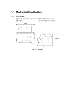
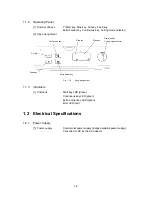
Page 5: ...Chapter 1 SPECIFICATIONS ...

Page 6: ...i CONTENTS Chapter 1 SPECIFICATIONS 1 1 Mechanical Specifications 1 1 1 1 1 Appearance 1 1 1 1 2 Operating Panel 1 2 1 1 3 Indicators 1 2 1 2 Electrical Specifications 1 2 1 2 1 Power Supply 1 2 ...

Page 7: ...1 1 1 1 Mechanical Specifications 1 1 1 Appearance 1 External dimensions W x D x H 468 mm x 387 mm x 273 mm 2 Weight Approx 8 3 kg main unit only 468 mm 387 mm 273 mm Fig 1 1 1 Appearance ...

Page 8: ...mode selector Continuous key Extra border key Feed key Cut key Start key Stop key Fig 1 1 2 Key Arrangement 1 1 3 Indicators 1 Positions Start key LED green Continuous key LED green Extra border key LED green Error LED red 1 2 Electrical Specifications 1 2 1 Power Supply 1 Power supply Commercial power supply locally available power supply Converted to DC by the AC adaptor ...

Page 9: ...Chapter 2 MECHANISMS ...

Page 10: ...1 Mechanical Operating Principles 2 1 2 1 1 Description of Mechanisms Border Mode 2 1 2 1 2 Feed and Compression Mechanisms 2 2 2 1 3 Cutter Mechanism Border Mode 2 5 2 1 4 Paper Size Detector Mechanism 2 7 2 1 5 Trimming Mechanism 2 9 ...

Page 11: ...ressed between the driving roller and sub roller 4 The compressed document and film is fed to the cutting area where it is cut to the document size detected by the paper size detector with borders added It is then transported to the next stage 5 The laminated document is fed out of the eject gate by the paper eject rollers Eject gate Y cutter blade Paper eject roller X cutter unit Paper eject sub ...

Page 12: ... the chassis to its prescribed position 2 As the Control cam gear rotates the LF change shaft is rotated to its prescribed position by the cam on the Control cam gear 3 A cam is mounted on the LF motor end of the LF change shaft at the left of the chassis As the LF change shaft rotates this cam rotates the two Gear holders at the left of the chassis which transmit the LF motor drive as shown in th...

Page 13: ... left of the chassis As the LF change shaft rotates this cam rotates the two Gear holders at the left of the chassis which transmit the LF motor drive as shown in the diagram 4 As a result of steps 1 to 3 above the drive is transmitted to the Driving roller that compresses the films During this operation the Paper feed roller and Paper eject roller rotate continuously to feed in documents and ejec...

Page 14: ...escribed position by the cam on the Control cam gear 3 A cam is mounted on the LF motor end of the LF change shaft at the left of the chassis As the LF change shaft rotates this cam rotates the two Gear holders at the left of the chassis which transmit the LF motor drive as shown in the diagram 4 As a result of steps 1 to 3 above the drive is transmitted to the Paper feed roller only A document is...

Page 15: ...ling edge are cut according to the document length S Y Cutter Vertical Drive Operation The SG motor drive rotates the Control cam gear to its prescribed position This rotation is transmitted via the YC lift arm and YC lift shaft to rotate the Y diversion lever and set the Y cutter to the cutting position Control cam gear YC lift arm Y diversion lever SG motor YC lift shaft Y cutter blade Fig 2 1 5...

Page 16: ... when the cut position at the trailing edge of the document reaches the cutting position of the rotary cutter and fixed blade cutter the feed rollers stop again 5 The document trailing edge is cut in the same way as the leading edge by a reciprocal movement of the rotary cutter attached to the carriage 6 The rotation of the Paper eject roller and Paper feed roller restarts to feed the laminated do...

Page 17: ...ot to turn on the Paper sensor and detect the document leading edge 2 When the trailing edge of the document passes out of the Paper feed rollers the Actuator top reverts to its original position to turn off the Paper sensor and detect the document trailing edge Paper feed sub roller Paper feed roller Actuator top Document feed surface Paper sensor Fig 2 1 7 Paper Length Detection ...

Page 18: ... Actuator Y which rotates about the pivot to switch off the Y CA sensor photosensor 2 When the Y CA sensor turns off the Y cutter arm movement stops and this position is detected as the document width Y sensor carriage Y CA sensor Y cutter arm Document Pivot Actuator Y Photosensor OFF status Photosensor ON status Fig 2 1 8 Paper Width Detection ...

Page 19: ...e Control cam gear in the direction of the arrow counterclockwise via a series of gears 3 Rotation of the Control cam gear forces the T cam roller to move vertically such that T lever also moves vertically rotating around its pivot 4 As T lever moves vertically the T cutter assy mounted on the end of T lever moves up and down trimming the corner of the laminated document into a rounded radius T ca...

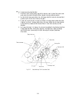
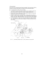
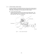
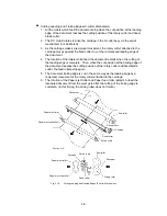
Page 20: ...Chapter 3 DISASSEMBLY PROCEDURES ...

Page 21: ...onnectors 3 12 3 4 2 Removing the PST PCB Paper Sensor PCB 3 13 3 4 3 Removing the Chassis Assy 3 14 3 5 PCBs 3 16 3 5 1 Removing the Main PCB 3 16 3 5 2 Removing the Jack PCB Assy 3 16 3 5 3 Removing the SW PCB Assy 3 17 3 6 X cutter Unit 3 18 3 6 1 Removing the X cutter Unit 3 18 3 6 2 Removing the Leaf Switch F Assy 3 18 3 7 Y CA Chassis Assy and Y cutter Arm 3 19 3 7 1 Removing the Y CA Chassi...

Page 22: ... Removing the Paper Eject Roller Unit 3 30 3 14 Y diversion Lever 3 31 3 14 1 Removing the Y diversion Lever Assy 3 31 3 15 Trimming Mechanism 3 32 3 15 1 Disassembling the Trimming Mechanism 3 32 3 16 Driving Roller 3 32 3 16 1 Removing the Driving Roller 3 32 3 17 Main Chassis B 3 33 3 17 1 Removing the Main Chassis B 3 33 3 17 2 Removing the Cassette Holder 3 34 3 17 3 Removing the ENC Sensor P...

Page 23: ... other heat producing tool ensure that heat does not damage wires circuit boards or plastic parts such as covers Take care not to lose small screws or washers removed when replacing parts As a safety precaution wear gloves when conducting disassembly operations 3 2 Removing the Film Cartridge 1 Open the top cover and move the Y cutter arm as far as possible to the left 2 Push the Set buttons R L i...

Page 24: ...cartridge Film cartridge Roller holder assy Fig 3 2 2 Removing the Film Cartridge 2 3 3 Covers 3 3 1 Removing the Trimmer Cover 1 Pull out the T cutter plate and the Trimmer bottom cover Trimmer bottom cover T cutter plate Fig 3 3 1 Removing the Trimmer cover 1 ...

Page 25: ...ver Trimmer cover screws Fig 3 3 2 Removing the Trimmer cover 2 3 3 2 Removing the Top Cover B Open the Top cover B Lift the Top cover B shafts out of the shaft recesses in the Body cover and remove Top cover B Top cover B Body cover Shaft recesses Shafts Fig 3 3 3 Removing the Top Cover B ...

Page 26: ...in the Body cover Remove the sub tray Body cover Shaft recesses Sub tray Fig 3 3 4 Removing the Sub tray 3 3 4 Removing Paper Tray A and Paper Guide 1 Flex the center of the top of Paper tray A in the direction of the arrow then release the left and right hooks Pull Paper tray A upward to remove it Paper tray A Fig 3 3 5 Removing Paper Tray A ...

Page 27: ...3 6 Removing the Paper Guide 3 3 5 Removing the Body Cover 1 Remove the two Bottom cover screws B from the bottom of the Bottom cover B And remove one screw from the surface of Body cover When inverting the unit to perform this work place it on a soft cloth to avoid scratching the cover Bottom cover screws B Soft cloth Fig 3 3 7 Removing the Body Cover 1 ...

Page 28: ... hook at the left and right side 4 Push on the Y diversion lever assy and release the two hooks from the front of the Body cover Body cover Side hooks Rear hooks A Bottom cover B Front hooks Y diversion lever assy B C Fig 3 3 8 Removing the Body Cover 2 5 Disconnect the Switch harness assy and the Cover switch assy connectors from the Main PCB and remove the Body cover Switch harness assy Cover sw...

Page 29: ...s at the rear of the Bottom cover B at the same time When inverting the unit to perform this work place it on a soft cloth to avoid scratching the cover Soft cloth Front cover screws Fig 3 3 10 Removing the Front Cover 1 2 Pull the front cover forward to remove it The Body cover must be removed before removing the Front cover Front cover Fig 3 3 11 Removing the Front Cover 2 ...

Page 30: ... lug from the Cassette holder 3 Slide Paper tray B in the direction of arrow B then lift it in the direction of arrow C to remove it Lug Cassette holder Paper tray B B A C Fig 3 3 12 Removing Paper Tray B 3 3 8 Removing the Back Cover 1 Remove the Back cover spring Back cover spring Back cover Body cover Fig 3 3 13 Removing the Back Cover 1 ...

Page 31: ... cover During this operation take care not to deform the film attached to the Back Cover Body cover Back cover Shafts Film Fig 3 3 14 Removing the Back Cover 2 3 3 9 Removing the Cover Switch 1 Remove the cover switch screw Remove the cover switch assy Cover switch screw Cover switch assy Fig 3 3 15 Removing the Cover Switch Assy ...

Page 32: ...B 2 Disconnect the Push SW assy 1 white and Push SW assy 2 red connectors from the SW PCB Take care not to apply force to the connectors between switch and harness in Push switch assy 1 and 2 Dial holder screws Push switch assy 1 and 2 Dial holder screws Dial switch holder assy Fig 3 3 16 Removing the Dial Switch Holder Assy ...

Page 33: ... red Before removing the Push SW assy 1 and 2 turn the Dial switch such that it does not touch the push switches mid point between Push SW assy 1 and Push SW assy 2 Take care not to apply force to the connectors between the Push switch and harness Push switch assy 1 and 2 Push switch screws Fig 3 3 17 Removing the Push Switches ...

Page 34: ...harness assy red black CN13 Power harness assy Fig 3 4 1 Removing the Harness Connectors 1 2 Disconnect the harnesses from the eight hooks on the Bottom cover B Fig 3 4 2 Removing the Harness Connectors 2 3 Peel off the tape that holds the harnesses inside the right of Bottom cover B then remove the harnesses from the Bottom cover B ...

Page 35: ...emoving the PST PCB Paper Sensor PCB Remove the PST PCB Paper sensor PCB screws from the Main chassis B then remove the PST PCB Paper sensor PCB PST PCB PST PCB screw Fig 3 4 3 Removing the PST PCB Paper Sensor PCB ...

Page 36: ... B Ground wire screw Ground wire Fig 3 4 4 Removing the Chassis Assy 1 2 Remove the two Bottom cover screws B and the washers from under the Bottom cover B When inverting the unit to perform this work place it on a soft cloth to avoid scratching the cover Bottom cover B Washers Bottom cover screws B Fig 3 4 5 Removing the Chassis Assy 2 ...

Page 37: ...our Bottom cover screws CL2000011 with four washers from under the Chassis assy Fig 3 4 6 Removing the Chassis Assy 3 4 Pull out the Chassis assy from Bottom cover Chassis assy Fig 3 4 7 Removing the Chassis Assy 4 Roller Holder Assy Bottom Cover Screw A ...

Page 38: ...emove the Main PCB Main PCB screw Main PCB screw Power harness assy Main PCB assy Fig 3 5 1 Removing the Main PCB 3 5 2 Removing the Jack PCB Assy Remove the Jack PCB screw and remove the Jack PCB assy The core shown in the diagram is fitted in the EU specification LX 300 only Jack PCB screw Jack PCB assy Fig 3 5 2 Removing the Jack PCB Assy ...

Page 39: ...crews Fig 3 5 3 Removing the Switch PCB Assy 1 2 Remove the Start key Stop key Two connection switch Continuous key and Extra border key The LED lenses can be removed from the Top cover by pushing them hard with a fine object such as a pen tip Start key LED lenses LED lens Stop key Continuous key Extra border key Two connection switch Fig 3 5 4 Removing the Switch PCB Assy 2 ...

Page 40: ...over when replacing the X cutter unit X cutter screws X cutter unit Y cutter assy Fig 3 6 1 Removing the X cutter Unit 3 6 2 Removing the Leaf Switch F Assy Remove the Leaf switch F screw then remove the Leaf switch F assy Take care not to bend the connector root on the Leaf switch F assy harness Leaf switch F assy Tape sensor holder X cutter unit Leaf switch F screw Fig 3 6 2 Removing the Leaf Sw...

Page 41: ...he Roller holder is locked remove the two Y CA chassis screws 3 Disengage the end of the Y cutter arm from the Y sensor carriage by moving it in direction A Remove the Y CA chassis assy Y sensor carriage Roller holder Y cutter arm Y CA chassis screws Y extension spring Y cutter arm A Fig 3 7 1 Removing the Y CA Chassis Assy ...

Page 42: ...g the Y CA Motor 3 7 3 Removing the Y cutter Arm 1 Remove the retaining ring from the Y cutter arm shaft pull out the Y cutter arm shaft and remove the Y cutter arm 2 Remove the Y CA arm screw then remove the Y CA arm Y CA arm Y cutter arm shaft Y cutter arm Y sensor carriage arm screw Retaining rings Fig 3 7 3 Removing the Y cutter Arm ...

Page 43: ...holder 2 Remove the two Y sensor rail screws 3 Disengage the tip of the Actuator top from the film hole then remove the Y sensor rail unit in the direction of the arrow Y sensor rail unit Cassette holder The tip of the Actuator top F cable Film Y sensor rail screw Fig 3 8 1 Removing the Y sensor Rail Unit ...

Page 44: ... Y sensor shaft 2 Remove the FPC holder A from the Y sensor rail then remove the Y sensor carriage Reinforcement film Y sensor shaft Retaining ring FPC holder Paper feed film FPC holder Y sensor carriage Y sensor rail screw Y sensor rail screw Retaining ring Y sensor rail Fig 3 8 2 Disassembling the Y sensor Rail Unit ...

Page 45: ...2 Remove the four Retaining rings two from the Roller holder two from the Paper feed holder then remove the Roller holder unit 3 Remove the plastic spacer from the rivet pins at each end of the Roller holder assy Spacer Retaining rings Roller holder unit Roller holder return spring Retaining rings Spacer Fig 3 9 1 Removing the Roller Holder Assy ...

Page 46: ...en remove the Paper feed roller unit Idle gear A Paper feed roller springs Idle gear A Double gear A Double gear B Roller gear AD Fig 3 10 1 Removing the Paper Feed Holder Assy 2 Rotate the Paper feed holder plates L R backward Remove the Paper feed holder plates L R by pulling the hooks out of the cut outs in the Chassis L R Paper feed holder plate R Paper feed holder plate L Fig 3 10 2 Removing ...

Page 47: ... the Actuator Top 3 11 Left Side of the Main Chassis 3 11 1 Removing the LF Motor 1 Remove the three LF motor holder screws then remove the LF motor holder assy and the three Spacers 2 Remove the two LF motor screws from the LF motor holder assy then remove the LF motor Spacer LF motor screw LF motor holder screw LF motor Fig 3 11 1 Removing the LF Motor ...

Page 48: ...10 3 4 6 Fig 3 11 2 Removing the Gears 2 Remove the two Gear holders simultaneously Remove the Gear holder spring from the Gear holders The Gear holder spring may be stretched if the Gear holders are removed separately Gear holder spring Idle gears B Gear holder Gear holder Fig 3 11 3 Removing the Gear Holders and Gear Holder Spring ...

Page 49: ...f switch SG assy 4 Remove the T lever shaft SG motor SG motor screws Idle gears A Chassis R support screw Leaf switch SG assy screw T lever shaft Leaf switch SG assy Chassis R support Fig 3 12 1 Removing the Right Side of the Chassis 1 5 Push down on the T lever unit to align the slot hole with the shaft then remove the unit T lever B T cam roller T lever spring Slot T lever unit T lever A Fig 3 1...

Page 50: ...he Chassis R support See Fig 3 12 1 3 12 2 Removing the YC Lift Shaft and LF Change Shaft 1 Remove the Paper eject roller springs 2 Remove the Y extension spring 3 Remove the Retaining ring for the YC lift shaft at the left side of the Main chassis Retaining ring Y extension springs Paper eject roller springs Fig 3 12 4 Removing the YC Lift Shaft and LF Change Shaft 1 ...

Page 51: ...t by pulling the right end of the YC lift shaft through the hole in Chassis R toward the middle of the chassis 6 Move the LF change shaft several millimeters toward the Main chassis R Remove the LF change shaft by pulling the right end of the shaft through the hole in Chassis R toward the middle of the chassis When pulling the right end of the YC lift shaft and LF change shaft through the hole in ...

Page 52: ... the Paper eject sub roller in exactly the same manner as the Paper eject roller move it toward the left then remove it from the right end Paper eject shaft holder Paper eject roller Paper eject sub roller Fig 3 13 1 Removing the Paper Eject Roller Unit 1 4 Remove the Paper eject roller bearing hook then remove the Paper eject roller bearing Hooks Paper eject roller bearings Fig 3 13 2 Removing th...

Page 53: ...3 31 3 14 Y diversion Lever 3 14 1 Removing the Y diversion Lever Assy 1 Lift the Y diversion lever assy to remove it Y diversion lever assy Fig 3 14 1 Removing the Y diversion Lever ...

Page 54: ...switch TRI assy T cutter screw T cutter unit Fig 3 15 1 Disassembling the Trimming Mechanism 3 16 Driving Roller 3 16 1 Removing the Driving Roller 1 Remove the Roller gear CD 2 Remove the Retaining ring push the Driving roller assy toward the left then remove it from the right end 3 Remove the Bearings R L Bearing R Roller gear CD Retaining ring Driving roller assy Retaining ring Bearing L Fig 3 ...

Page 55: ...B 3 Remove the tape holding the ENC sensor harness 4 Remove the Leaf switch C3 C4 screws then remove the Leaf switch C3 C4 assemblies 5 Remove the two Cassette actuators Edging saddle Leaf switch C4 screw Cassette holder Rear of the main chassis B Tape Harness ENC sensor ENC sensor harness The bottom face of cassette holder Leaf switch C3 screw Leaf switch C4 assy Leaf switch C3 assy Cassette actu...

Page 56: ... Cassette holder 2 Pull out the Cassette holder in the direction of the arrow Hooks Fig 3 17 2 Removing the Cassette Holder 3 17 3 Removing the ENC Sensor PCB Remove the ENC sensor PCB screw then remove the ENC sensor assy ENC sensor assy ENC sensor PCB screw Fig 3 17 3 Removing the ENC Sensor PCB ...

Page 57: ... and F Remove the ten Side chassis screws five each side then remove the Main chassis L R and F Main chassis L Side chassis screws Main chassis F Main chassis R Main chassis B Side chassis screws Fig 3 17 4 Removing the Main Chassis L R and F ...

Page 58: ...Chapter 4 ASSEMBLY PROCEDURES ...

Page 59: ...Lift Shaft and LF Change Shaft 4 10 4 7 2 Installing the Right Side of the Chassis 4 11 4 8 Left Side of the Chassis 4 14 4 8 1 Installing the Gears 4 14 4 8 2 Installing the LF Motor 4 15 4 9 Paper Feed Roller 4 16 4 9 1 Installing the Paper Feed Holder Assy and the Paper Feed Roller Assy 4 16 4 10 Roller Holder Assy 4 19 4 10 1 Installing the Roller Holder Assy 4 19 4 11 Y sensor Rail Unit 4 20 ...

Page 60: ... Assy 4 33 4 17 3 Installing the Cover Switch 4 35 4 17 4 Installing the Back Cover 4 35 4 17 5 Installing Paper Tray B 4 36 4 17 6 Installing the Front Cover 4 36 4 17 7 Installing the Body Cover 4 37 4 17 8 Installing the Paper Tray A and Paper Guide 4 39 4 17 9 Installing the Sub tray 4 40 4 17 10Installing the Top Cover B 4 41 4 17 11Installing the Trimmer Upper Cover 4 41 4 18 Installing the ...

Page 61: ...e transporting a circuit board wrap it in a conducting sheet such as aluminum foil When using a soldering iron or other heat producing tool ensure that heat does not damage wires circuit boards or plastic parts such as covers Take care not to lose small screws or washers installed when replacing parts Tighten all screws to the torque specified in the table below As a safety precaution wear gloves ...

Page 62: ...kgf cm Y CA motor screw 1 SCREW FLANGED M2 6 5 0 196 to 0 392 N m 2 to 4 kgf cm Sensor holder screw 1 TAPTITE CUP M3 5 0 49 to 0 686 N m 5 to 7 kgf cm Y CA chassis screw 2 TAPTITE CUP M3 5 0 49 to 0 686 N m 5 to 7 kgf cm Switch PCB screw 8 TAPTITE BIND B M3 12 0 49 to 0 686 N m 5 to 7 kgf cm Jack PCB screw 1 TAPTITE BIND B M3 8 0 49 to 0 686 N m 5 to 7 kgf cm Main PCB screw 4 TAPTITE BIND B M3 8 0...

Page 63: ... chassis B Main chassis L Main chassis B Edging saddle Side chassis screws Main chassis F Main chassis R Side chassis screws Fig 4 3 1 Installing the Main Chassis L R and F 4 3 2 Installing the ENC Sensor PCB Align the boss on the ENC sensor PCB assy Attach the ENC sensor PCB assy to the Cassette holder with the ENC sensor PCB screw Pass the ENC sensor harness through the hole in the Cassette hold...

Page 64: ...he hole in the bottom of Main chassis B 2 Insert the lugs at the front of the Cassette holder and click the hooks at the rear onto Main chassis B Hooks Lugs ENC sensor PCB assy Main chassis B Harness Fig 4 3 3 Installing the Cassette Holder Chassis R L and F are omitted for explanation ...

Page 65: ...er the Cassette holder then pass it through the Edging saddle under the Chassis B Cassette holder ENC sensor ENC sensor harness Leaf switch C3 C4 assy Leaf switch C4 screws Hook Cassette actuator Harness Leaf switch C3 assy Tape The bottom face of Cassette holder Fig 4 3 4 Installing the Main Chassis B 4 Tape the ENC sensor PCB harness inside the marked line the side of the Cassette holder hooks u...

Page 66: ...arings L R into the Driving roller Mount it sequentially into Main chassis L and Main chassis R 3 After installing Bearings L R into the Main chassis L R attach the Retaining ring to the left end of the Driving roller assy 4 Install the Roller gear CD Retaining ring Driving roller assy Bearing L Bearing R Roller gear CD Retaining ring Fig 4 4 1 Installing the Driving Roller ...

Page 67: ...Engage the harness into the hook under the Cassette holder then fix it with tape on the two marked areas Chassis B front face and Chassis R inside surface 3 Align the T cutter assy with the boss holes and install it with the T cutter screw T cutter screw Leaf switch TRI screw Leaf switch TRI assy T cutter assy The bottom face of cassette holder Leaf switch TRI harness Fig 4 5 1 Assembling the Trim...

Page 68: ...n chassis F Y diversion lever assy Fig 4 6 1 Installing the Y diversion Lever 1 2 Install the Paper eject roller bearings such that the Y diversion lever arms are sandwiched between the Paper eject roller bearing and the Main chassis L R Fasten the Paper eject roller bearings with the Hooks both L R Fig 4 6 2 Installing the Y diversion Lever 2 Paper eject roller bearings Hook ...

Page 69: ...lders outward to engage with the groove in the Paper eject roller 3 Move the paper eject sub roller to the left then to the right to insert it into the Paper eject shaft holders and the Paper eject roller bearings Paper eject roller Paper eject shaft holder Paper eject roller bearings Paper eject sub roller Fig 4 6 3 Installing the Paper Eject Roller 1 4 Align the grooves in the Paper eject roller...

Page 70: ...C lift shaft into the Main chassis L and attach the retaining ring outside Chassis L YC lift arm LF change shaft Boss YC lift shaft YC lift shaft Retaining ring ain Chassis L side Groove Fig 4 7 1 Installing the YC Lift Shaft and LF Change Shaft 1 4 Attach the Y extension springs between the hooks inside the Main chassis L R and the Y diversion lever 5 Attach the Paper eject roller springs between...

Page 71: ...nd YC lift arm is inserted correctly into the grooves in the Control cam gear The bosses are correctly inserted if the Control cam gear rotates smoothly when the Y diversion lever is pressed Fig 4 7 3 Installing the Right Side of the Chassis 1 4 Install the T lever A to the Main chassis R T lever A Main chassis R T cutter assy Fig 4 7 4 Installing the Right Side of the Chassis 2 Control cam gear T...

Page 72: ...stalling the Right Side of the Chassis 3 6 Insert the T lever shaft into the shaft holes in the Main chassis R and T lever A B Push in the T lever shaft until the groove in the shaft engages with the hook on the T cutter assy T lever A T cutter assy Groove T lever B T lever shaft Fig 4 7 6 Installing the Right Side of the Chassis 4 ...

Page 73: ...tion where it cannot interfere with the Leaf switch 8 Install the SG motor with the two SG motor A screws 9 Install the Idle gears A 10 Attach the Chassis R support with the Chassis R support screw SG motor SG motor screws A Chassis R support screw Chassis R support Idle gears A Leaf switch SG assy screw Leaf switch SG assy Fig 4 7 7 Installing the Right Side of the Chassis 5 ...

Page 74: ...en attach the Gear holder springs Gear holder spring Gear holders Fig 4 8 1 Installing the Gears 1 2 Install the gears according to the sequence shown in the diagram below Push the shaft into a gear or holder with a hook until the hook engages 5 7 Gear holders 9 10 3 11 4 2 1 4 6 8 Fig 4 8 2 Installing the Gears 2 ...

Page 75: ...e LF motor holder assy Put the Spacers over the three protruding screws Mount the LF motor holder assy to the Main chassis L Fix the LF motor holder to the positioning pins then fasten it firmly and correctly in place with the screws LF motor holder Main chassis L Spacer LF motor LF motor screw LF motor holder screw Fig 4 8 3 Installing the LF Motor ...

Page 76: ...er Assy 1 Attach the Paper feed holder plates L with shaft and R to the Main chassis L and R Assemble with the hooks on the Paper feed holder plates L R engaged in the cut outs in the Chassis L R Paper feed holder plate R Paper feed holder plate L Fig 4 9 1 Installing the Paper Feed Holder Assy ...

Page 77: ...s through the slots in the Paper feed holder plates L and R Ensure that the Actuator top fits into Part A of the Cassette holder Sub bearing Bearing Paper feed roller assy Paper feed sub roller Actuator top Sub bearing Bearing Paper feed holder plate R Part A Actuator top Slot per feed holder plate L Slot Cassette Holder Fig 4 9 2 Installing the Paper Feed Roller Assy 1 ...

Page 78: ...older plate R Sub bearing Paper feed roller spring Fig 4 9 3 Installing the Paper Feed Roller Assy 2 5 Attach the two Idle gears A one Double gear B one Double gear A and the Roller gear AD to the Paper feed holder plate L Double gear B Roller gear AD Double gear A Idle gear A Idle gear A Fig 4 9 4 Installing the Paper Feed Roller Assy 3 ...

Page 79: ...t pins on the roller holder unit through the curved slots on the Main chassis L and R and the slots on top of the Paper feed roller plate 4 Fasten the Roller holder in position with the four Retaining rings 5 Install the Roller holder return spring while the Roller holder unit is open Spacer Roller holder assy Main chassis shafts Retaining rings Roller holder return spring Retaining ring Retaining...

Page 80: ...t cable to the dimensions shown in the diagram below Approx 350mm Fig 4 11 1 Bending the Sensor Flat Cable to the Dimensions 2 Attach the FPC holders A to the flat cable 3 Locate the sensor flat cable inside the Y sensor rail unit FPC holder A FPC holder A Approx 170 mm Approx 25 mm Fig 4 11 2 Sensor Flat Cable Location ...

Page 81: ...or rail and Y sensor carriage and fasten with a Retaining ring at each end 7 Check that the sensor cable is not tight when the Y sensor carriage is moved to the left end as shown in the diagram below Film Retaining ring FPC holder A Y sensor shaft Y CA sensor carriage Slot Y sensor rail Retaining ring Reinforcement film Slot FPC holder A Fig 4 11 3 Assembling the Y sensor Rail Unit ...

Page 82: ...and Paper feed sub roller during installation Pass the part of the Paper feed film with the Reinforcement film attached between the Paper feed roller and Paper feed sub roller then pass the end of the Actuator top through the hole in the Paper feed film Y sensor rail screw Y sensor rail unit Film Paper feed film The end of the Actuator top Paper feed roller Paper feed sub roller Fig 4 11 4 Assembl...

Page 83: ... the Y CA arm screw Y cutter arm Y sensor carriage arm Y CA arm screw Fig 4 12 1 Installing the Y cutter Arm 1 2 Pass the Y cutter arm shaft through the Y CA chassis assy and Y cutter arm and fasten with a Retaining ring at each end Y CA chassis assy Y cutter arm Y cutter arm shaft Retaining rings Fig 4 12 2 Installing the Y cutter Arm 2 ...

Page 84: ...he Y CA motor screws Y CA chassis assy Y CA motor Y CA motor screw Fig 4 12 3 Installing the Y CA Motor 4 12 3 Installing the Y CA Chassis Assy 1 Insert the end of the Y cutter arm into the Y sensor carriage Y sensor carriage arm Y sensor carriage Fig 4 12 4 Installing the Y CA Chassis Assy 1 ...

Page 85: ...e two Y CA chassis screws Set the left and right Embosses into the holes in the Y CA chassis before tightening the screws 5 Attach the Y extension spring to the Y diversion lever and the Y CA chassis assy Y cutter guide L Part A Y CA sensor carriage Y cutter arm Y CA timing belt Y cutter arm Y CA chassis assy Y extension spring Y CA chassis screws Fig 4 12 5 Installing the Y CA Chassis Assy 2 ...

Page 86: ...r X cutter unit Sensor holder Sensor holder screw Leaf switch F screw Leaf switch F assy Fig 4 13 1 Installing the Leaf Switch F Assy 4 13 2 Installing the X cutter Unit Slide the X cutter unit into position from the right side of the main unit and fasten it in position with the two X cutter screws X cutter unit X cutter screws Fig 4 13 2 Installing the X cutter Unit ...

Page 87: ...ses Attach the following harnesses to the Main chassis B Edging saddle SG motor harness black ENC harness assy white Leaf switch TRI harnesses black x 2 Leaf switch C3 red C4 yellow harness Harnesses Edging saddle Fig 4 14 1 Installing the Harnesses ...

Page 88: ...ew Fig 4 15 1 Installing the Jack PCB Assy 4 15 2 Installing Main PCB Assy 1 1 Install the Main PCB assy 1 to the Bottom cover with the four Main PCB screws On a newly supplied part cut away the PST SENSOR PCB assy 2 Attach the Jack PCB Power harness assy red black to the Main PCB assy 1 Power harness assy Main PCB screws Main PCB screws PST SENSOR PCB assy Main PCB assy Fig 4 15 2 Installing Main...

Page 89: ...tom cover B Fasten it with the four Bottom cover screws A with four washers Fig 4 16 1 Installing the Chassis Assy 1 2 Install the Chassis assy under the Bottom cover B using the two Bottom cover screws B and Spring washers Soft cloth Bottom cover B Bottom cover screws B Fig 4 16 2 Installing the Chassis Assy 2 Bottom cover screws A ...

Page 90: ...ssy 3 The Chassis perpendicularity must be adjusted after the Chassis assy is installed to the Bottom cover See Section 6 Maintenance 4 16 2 Installing the PST SENSOR PCB Assy Attach the PST SENSOR PCB assy to the Main chassis B with the PST SENSOR PCB screws PST SENSOR PCB assy PST SENSOR PCB screw Main chassis B Fig 4 16 4 Installing the PST SENSOR PCB Assy ...

Page 91: ...ough the three harness retainers 4 Install the F cable as shown in the diagram below Yellow 2P White 4P 4 Yellow blue white red gray 5P Black 6P Installation of the 1 3 4 harnesses F cable 5 Black 4P Tape Installation of the 2 harness Red 2P 3 Blue 2P 1 Orange 2P Black 2P 2 Red 5P Harness retainers White 2P Insert the core with the harness wound on it to the rib in the cover FPC holder A Pass the ...

Page 92: ... 1 Installing the Push SW Assy Attach the Push SW assy 1 and Push SW assy 2 to the Dial switch holder with the Push switch screws Push SW screws Dial switch holder Push SW assy 1 and 2 Fig 4 17 1 Installing the Push SW Assy ...

Page 93: ...W assy 1 Harness connector white Switch PCB Fig 4 17 2 Installing the Dial Switch Holder Assy 1 2 Turn over the Body cover and attach the Start key Stop key Two connection switch Continuous key and Extra border key Check that the LED lenses are correctly aligned with the front of the cover Start key LED lens LED lenses Continuous key Stop key Extra border key Two connection switch Fig 4 17 3 Insta...

Page 94: ...B screws Switch PCB assy Fig 4 17 4 Installing the Dial Switch Holder Assy 3 4 Attach the Dial switch holder assy to the Body cover with the Dial switch holder screws Dial switch holder screws Body cover Dial switch holder assy Dial switch holder screws Fig 4 17 5 Installing the Dial Switch Holder Assy 4 ...

Page 95: ...side the right of the Body cover and fasten them with the hooks Part A Cover switch assy Section A Body cover Cover switch screw Dial switch holder assy Fig 4 17 6 Installing the Cover Switch 4 17 4 Installing the Back Cover 1 Install the Back cover by flexing the cover and inserting the shafts into the shaft recesses in the Body cover 2 Install the Back cover spring Back cover spring Body cover B...

Page 96: ...Lug Paper tray B Lug A Cassette holder Fig 4 17 1 Installing Paper Tray B 2 Insert the Tray B stopper onto the Paper feed roller 4 17 6 Installing the Front Cover 1 Align the hooks at the bottom and insert the Front cover Hooks Front cover Fig 4 17 1 Installing the Front Cover 1 Paper feed roller Tray B stopper Paper tray After assembling Paper Tray B with Paper feed roller insert Tray B stopper o...

Page 97: ... the rear Soft cloth Front cover screws Fig 4 17 10 Installing the Front Cover 2 4 17 7 Installing the Body Cover 1 Connect the Switch harness assy and the Cover SW assy to the Main PCB Cover switch harness Switch harness assy Fig 4 17 11 Installing the Body Cover 1 ...

Page 98: ...er down while holding down the Y diversion lever Take care not to apply too much force Not much force is required if Step 3 is conducted correctly 5 Check that the two hooks at the front of the Body cover are engaged Repeat from step 2 if the hooks are not engaged 6 Check that the two hooks at the sides of the Body cover are engaged Press down on Part A if the hooks are not engaged 7 Push down the...

Page 99: ...form this work place it on a soft cloth to avoid scratching the cover Bottom cover screws A Soft cloth Fig 4 17 14 Installing the Body Cover 4 4 17 8 Installing the Paper Tray A and Paper Guide 1 Engage the hooks at the rear of the Paper guide into the grooves in Paper tray A Paper tray Paper guide Hooks Fig 4 17 15 Installing the Paper Guide ...

Page 100: ...ig 4 17 16 Installing the Paper Tray 4 17 9 Installing the Sub tray Flex the center of the Sub tray toward you and insert the shafts into the shaft recesses in the Body cover to install the Sub tray The Sub tray can be folded in the direction of the arrow Sub tray Body cover Shaft recess Fig 4 17 17 Installing the Sub tray ...

Page 101: ... recess Shafts Body cover Fig 4 17 18 Installing the Top Cover B 4 17 11 Installing the Trimmer Upper Cover 1 Insert Part A of the Chassis into Part B of the Trimmer upper cover Align the two bosses and fasten the cover with the two Trimmer upper cover screws Chassis Bosses Part A of the Chassis Trimmer upper cover screws Part B Trimmer upper cover Fig 4 17 19 Installing the Trimmer Cover 1 ...

Page 102: ...bottom cover Trimmer bottom cover T cutter plate Fig 4 17 20 Installing the Trimmer Cover 2 4 18 Installing the Y cutter Slide the Y cutters from each end of the Y diversion lever and pull them upward to install them Y diversion lever Y cutters Z Fig 4 18 1 Installing the Y cutter ...

Page 103: ...r holder assy Roller holder assy Tape cassette Fig 4 19 1 Installing the Film Cartridge 1 2 Push the Set buttons R L to lock the Roller holder assy Close the Top cover Set buttons L R Top cover Fig 4 19 2 Installing the Film Cartridge 2 For a detailed description how to install the Film cartridge see 6 2 1 Replacing the Cartridge in Section 6 Maintenance ...

Page 104: ...tte Attachment 1 Insert the A4 A6 cassette attachment with the handle at the left 2 Follow the method described for the A3 cartridge to insert the A4 A6 cartridge A4 A6 cassette attachment Fig 4 19 3 Installing the A4 A6 Cassette Attachment ...

Page 105: ...Chapter 5 ELECTRONIC CONTROLLERS ...

Page 106: ...1 Electronic Parts 5 1 5 1 1 Configuration of the Electronic Parts 5 1 5 1 2 Outline of the Electronic Parts 5 2 5 2 Operation of Each Part 5 3 5 3 Main PCB 5 4 5 4 Detector Circuits 5 10 5 5 Motor Drive Circuits 5 16 5 6 Power Supply Circuits 5 19 ...

Page 107: ...arts The electronic parts of the unit comprise the following PCBs and an AC adaptor S Main PCB S Switch PCB S Jack PCB S Paper size sensor PCB Y CA sensor PCB S ENC PCB S Document Detect PCB PST sensor PCB S AC adaptor Fig 5 1 1 Configuration of the Electronic Parts ...

Page 108: ...Stop key Continuous key and Extra border key LEDs to indicate power ON continuous mode extra and errors and connectors to connect to push switches of dial switch S Jack PCB The Jack PCB is located at the jack input at the rear of the bottom cover It supplies unstabilized DC voltages from the AC adaptor to the Main PCB S Paper size sensor PCB Y CA sensor PCB The Paper size sensor PCB is located on ...

Page 109: ...epping motor A single trimming operation is completed by 266 steps in the reverse direction from the home position then 266 steps in the forward direction Selection between document feed film feed and film ejection occurs within 515 steps from the home position The Y cutter vertical movement requires approximately 407 steps S Y CA motor This motor moves the Y carriage to the edge of the document T...

Page 110: ...ing switch status detection motor drive circuits and power circuits Fig 5 3 1 Block Diagram of the Electrical Parts S Main CPU The main CPU is an 8 bit CMOS microcontroller that controls the overall system The main CPU incorporates 1 kB RAM 32 kB ROM and 72 I O ports The I O map for the I O ports is shown in Table 5 3 1 overleaf ...

Page 111: ...P22 5 IN X CUT1 P21 6 IN N C P20 8 IN CASSETTE SIZE A4 P36 79 OUT 30mA ENC1 LED P35 78 OUT 30mA ENC LED P34 77 OUT 30mA LED 1 P33 76 OUT 30mA LED 2 P32 75 OUT 30mA PST LED P31 74 OUT 30mA YCA LED P30 73 OUT 30mA LED 4 P47 48 OUT SG MOTOR PHASE A P46 47 OUT SG MOTOR PHASE B P45 46 OUT SG MOTOR PHASE C P44 45 OUT SG MOTOR PHASE D P43 44 OUT YA MOTOR PHASE A P42 43 OUT YA MOTOR PHASE B P41 42 OUT YA ...

Page 112: ...PST P72 51 IN YCA P71 50 OUT N C P70 49 OUT N C P87 64 IN SP1 P86 63 IN SP2 P85 62 IN SP3 P84 61 IN SP4 P83 60 IN SP5 P82 59 IN SP6 P81 58 IN SP7 P80 57 IN SP8 P97 16 OUT N C P96 15 OUT N C P95 14 IN KI2 P94 13 IN KI1 P93 12 IN KI0 P92 11 OUT KO2 P91 10 OUT KO1 P90 9 OUT KO0 XIN 3 IN XIN XOUT 2 OUT XOUT RESET 4 IN RESET TEST 7 IN TEST VDD 40 VDD VSS 1 VSS VAREF 39 VAREF VASS 38 VASS ...

Page 113: ...rned ON or OFF S 80943ANMP DD7 is used as the reset IC in this circuit When the power is turned ON the reset IC holds the reset output Low for approximately 5 ms after the 5V DC power supply applied voltage reaches 4 3 V After this period the reset output becomes High to clear the main CPU reset status When the power is turned OFF after the 5V DC power supply applied voltage drops to 4 3 V or belo...

Page 114: ...gh level using R69 in the input mode Fig 5 3 4 Buzzer Drive Circuit S LED Drive Circuit This circuit drives the four LED indicators mounted on the Switch PCB The LED4 LED2 and LED1 are directly driven by the high current ports P30 P33 and P34 on the main CPU The main CPU output port P52 lights LED3 via Q1 The LED lights when the output is Low When not lit the LED is in the high impedance status an...

Page 115: ...the unit Two connection switch Start key Stop key Dial switch Continuous key and Extra border key and the sensors that determine the film type document length and width and cover open closed status The Main CPU controls the motors LEDs and buzzer according to these input signals S Motor Drive Circuits These circuits convert the motor control signals output from the main CPU output ports to 24V dri...

Page 116: ...h and sensor are listed below In addition a separate switch to detect the motor initial status is also mounted Switch scan circuit Two connection switch Continuous key Extra border key Start key and Stop key Dial switch circuit RSW1 RSW2 switches Cover switch circuit Cover switch Paper width detector circuit YCA F sensor Paper length detector circuit PST switch Cartridge type detector circuit CSIZ...

Page 117: ...m intervals but the document and tape are fed continuously while the Feed switch is held down When the main CPU detects that the CUT switch was pressed it operates the X cutter to start the film cutting operation When the main CPU detects that the TRI switch was pressed it starts the trimming operation When the main CPU detects that the Start switch was pressed it starts feeding and compressing th...

Page 118: ...statuses corresponding to each of the following permutations RSW1 OFF and RSW2 OFF RSW1 ON and RSW2 OFF RSW1 OFF and RSW2 ON or RSW1 ON and RSW2 ON Fig 5 4 2 Dial Switch Circuit S Cover Switch Circuit This circuit detects whether the cover is open or closed The cover switch is located in the center of the body cover The signal detected by the cover switch leaf switch is input to the Main PCB via t...

Page 119: ... where the Actuator Y having cut off the photosensor Y CA sensor comes off the photosensor thereby detecting the edge of the document Also determines the Y carriage Y cutter position meeting the selected Auto Cut mode status When the document edge is detected the main CPU input signal P72 YCA F becomes Low However as P31 is normally at High impedance status the photosensor Y CA sensor does not ope...

Page 120: ... presses the Cartridge type detector switch CSIZE4 and turns it ON P20 becomes LOW The Cartridge type detector switches remain OFF when an A6 film cartridge is inserted and when no film cartridge is inserted Fig 5 4 6 Cartridge Type Detector Circuit Film Type Detector Circuit S Film Type Detector circuit ENC sensor PCB This circuit detects the type of film This circuit comprises a reflective photo...

Page 121: ...ilm feed detector switch TPS and sets the ON input Low Fig 5 4 8 Film Feed Detector Circuit S Input Voltage Detector Circuit This circuit detects the AC adaptor output voltage to prevent danger due to an AC adaptor that is faulty or incorrectly inserted The AC adapter output voltage is split by R25 and R50 and input to the CPU A D converter port P60 The CPU detects the AC adapter output voltage fr...

Page 122: ...1 and the Paper feed motor is controlled by Driver 6 The Paper feed motor current limit values can be switched using P00 P05 and P06 Fig 5 5 1 Paper Feed Motor Drive Circuit S SG Motor Drive Circuit This circuit drives the SG motor using 2 2 phase excitation from the 24 VDC stabilized constant voltage The stepping motor excitation phases A B C and D are controlled by main CPU ports P47 P46 P45 and...

Page 123: ...se excitation from the 24V DC stabilized constant voltage and maintains a low voltage during LF motor operation The stepping motor excitation phases A B C and D are controlled by main CPU ports P43 P42 P41 and P40 respectively The seven transistor arrays incorporated into 5 drive the Y CA motor The drive voltage is controlled by the main CPU port P54 which applies 24V DC to the Y CA motor through ...

Page 124: ...n CPU ports P64 to P67 and is driven by the DC motor control circuit The two switches are detected by ports P22 and P23 The operation of the DC motor for each control port status is listed in Table 5 5 1 Table 5 5 1 DC Motor Control P67 P66 P65 P64 DC Motor Drive High Low Low High TURN LEFT Low High High Low TURN RIGHT High Low High Low BRAKE Low Low Low Low OFF Fig 5 5 5 X cutter Motor Drive Circ...

Page 125: ...the AC adaptor through the Jack PCB via fuse F1 protective circuit and the filter circuit The 2 channel switching power IC IC 1 in the circuits converts the unstabilized DC voltage into a stabilized 5V voltage logic power supply and into a stabilized 24V DC voltage drive power supply Fig 5 6 1 Power Supply Circuits ...

Page 126: ...load current to create a stable supply This control is conducted in the power IC Fig 5 6 2 5V Power Supply S 24V Power Supply Fig 5 6 3 shows the timing chart for the 24V DC power supply during idling In this circuit the transistor Q5 switches at approximately 100 kHz to convert the unstabilized input voltage to a stabilized 24V supply When transistor Q5 is ON energy accumulates in the coil L2 Whe...

Page 127: ...Chapter 6 MAINTENANCE ...

Page 128: ...3 Lubrication Positions 6 1 6 2 Replacing the Cartridge and Film 6 12 6 2 1 Replacing the Cartridge 6 12 6 2 2 Replacing the Sheet 6 15 6 3 Adjustments 6 18 6 3 1 Adjusting the Right Y cutting Position Border Mode 6 18 6 3 2 Adjusting the Left Y cutting Position 6 19 6 3 3 Adjusting Perpendicularity of Chassis and Document 6 20 ...

Page 129: ...he codes in the table below are used in the descriptions in section 6 1 3 Code Lubricant Name E Epinoc grease 1 S Silicon grease KS64F 6 1 2 Precautions during Lubrication Do not apply lubricant to parts other than the specified parts The lubricant may adversely affect plastic parts or PCBs Take care not to apply too much lubricant which can then drip onto other parts As a guideline apply a drop t...

Page 130: ...10 CL2000016 Apply lubricant to inside of cam groove on Control Cam Gear Fig 6 1 2 Cam Groove on Side of Control Cam Gear LF motor gear 1 position LF motor gear Fig 6 1 3 LF Motor Gear SG motor gear 1 position SG motor gear Fig 6 1 4 SG Motor Gear Control Cam Gear ...

Page 131: ...er shaft Fig 6 1 5 Roller Holder Shaft Sliding surfaces of sub roller shafts in Bearings R L 4 positions Bearings R L Fig 6 1 6 Sliding Surfaces of Sub Roller Shafts in Bearings R L Engaged parts of YC lift shaft 2 positions YC lift shaft Fig 6 1 7 Engaged Parts of YC Lift Shaft ...

Page 132: ...1 8 Link Between YC Lift Shaft and YC Lift Arm Engaged parts of LF change shaft 2 positions LF change shaft Fig 6 1 9 Engaged Parts of LF Change Shaft Gear holder change cam surface on LF change shaft 2 position LF change shaft Fig 6 1 10 Gear Holder Change Cam Surface on LF Change Shaft ...

Page 133: ...er Holder Sub roller shaft bearings 2 positions Sub roller shaft bearing Fig 6 1 11 Sub Roller Shaft Bearings Roller holder spring mounting 1 position Roller holder spring Fig 6 1 12 Roller Holder Spring Mounting ...

Page 134: ...6 6 S Y cutter Arm Y cutter arm shaft 1 position Y cutter arm shaft Fig 6 1 13 Y cutter Arm Shaft Y sensor shaft 1 position Y sensor carriage Y sensor shaft Fig 6 1 14 Y sensor Shaft ...

Page 135: ...per Feed Roller and Paper Feed Sub roller Shafts Sliding surfaces of Paper feed sub roller shaft holder shafts 4 positions Paper feed sub roller Fig 6 1 16 Sliding Surfaces of Paper Feed Sub roller Shaft Holder Shafts Paper tray B shaft bearings 4 positions Paper tray B Fig 6 1 17 Paper Tray B Shaft Bearings ...

Page 136: ...Paper feed sub roller Paper feed roller Chassis B Paper feed roller spring Fig 6 1 18 Left right Contact Points Between Paper Feed Roller Spring and Chassis B S Driving Roller Driving roller shaft bearings 2 positions Driving roller shaft bearing R L Fig 6 1 19 Driving Roller Shaft Bearings ...

Page 137: ...s 4 positions Paper eject roller bearing Fig 6 1 20 Paper Eject Roller and Paper Eject Sub roller Shaft Bearings Sliding surfaces of Paper eject roller shaft holder shafts 4 positions Paper eject roller shaft holder Fig 6 1 21 Sliding Surfaces of Paper Eject Roller Shaft Holder Shafts ...

Page 138: ...00010 Sliding surfaces of T cutter unit and T paper guide 6 positions Fig 6 1 22 Sliding Surfaces of T cutter Unit and T paper Guide Rotation points of T lever A 2 positions T lever A Fig 6 1 23 Rotation Points of T lever A ...

Page 139: ...de shaft 1 position Y cutter guide shaft Y diversion lever Fig 6 1 24 Y cutter Guide Shaft Sliding surfaces of Y diversion lever and YC lift shaft 2 positions YC lift shaft Fig 6 1 25 Sliding Surfaces of Y diversion Lever and YC Lift Shaft ...

Page 140: ...power switch and open the top cover Fig 6 2 1 Replacing the Cartridge 1 2 Push the Set buttons R L in the direction indicated by the arrow to unlock the Roller holder assy Hold the Set buttons and lift the Roller holder assy Set buttons R L Set buttons Fig 6 2 2 Replacing the Cartridge 2 ...

Page 141: ...stall the new cartridge Check the following items before inserting the cartridge Cartridge shutter is fully closed The edge of the sheet is parallel with the cartridge film outlet If the edge is not parallel cut it parallel with scissors See page 6 17 Fig 6 2 4 Replacing the Cartridge 4 ...

Page 142: ...lacing the Cartridge 5 6 Close the top cover Fig 6 2 6 Replacing the Cartridge 6 7 Turn on the power switch and press the Feed key to feed out some sheet and remove the slackness in the sheet Hold down the Feed key until the edge of the sheet reaches the eject gate 8 Press the Cut key to cut off the end of the sheet fed out to remove the slackness ...

Page 143: ... the Sheet 1 Carefully remove the cartridge Fig 6 2 7 Replacing the Sheet 1 2 Open the cartridge shutter then open the cartridge cover Fig 6 2 8 Replacing the Sheet 2 3 Remove the old sheet Fig 6 2 9 Replacing the Sheet 3 ...

Page 144: ...into the cartridge as shown in the diagram It is not possible to insert the film in the wrong direction Fig 6 2 10 Replacing the Sheet 4 5 Detach the plastic holders in the direction of the arrow Fig 6 2 11 Replacing the Sheet 5 6 Close the cartridge cover ensuring that the edge of the sheet protrudes from the cartridge film outlet Fig 6 2 12 Replacing the Sheet 6 ...

Page 145: ...ge of the sheet is parallel with the cartridge film outlet If the edge is not parallel cut it parallel with scissors Fig 6 2 14 Replacing the Sheet 8 9 Gently insert the cartridge Fig 6 2 15 Replacing the Sheet 9 Note After removing sheet from its sealed pack it will dry up if not inserted into the cartridge ...

Page 146: ... cutter attached to the Y cutter guide to adjust the cutting position for the right edge of the film In the diagram below move the Adjustment plate to the right to increase the margin between the film and the document 5 After adjustment tighten Screw 2 then tighten Screw 1 Laminate a test document to check if the amount of border has improved 6 Repeat steps 2 to 5 until the borders are correct If ...

Page 147: ...e cutting position for the left edge of the film In the diagram below move Y sensor carriage arm to the right to increase the margin between the film and the document 4 After adjustment tighten the Screw Laminate a test document to check if the amount of border has improved 5 Repeat steps 2 to 4 until the borders are correct If the left border is adjusted in the Border Mode the No Border mode is a...

Page 148: ...the square holes in the Chassis and bosses protruding from the Bottom cover Push the Chassis into position in the direction of the arrow shown in the diagram 3 Taking care not to displace the Chassis tighten the screws A and A Remove the jig and tighten the remaining two screws Fig 6 3 3 Adjusting Perpendicularity of Chassis and Document Paper Feed Roller Square Hole Boss Screws X Cutter Screws Ji...

Page 149: ...Chapter 7 TROUBLESHOOTING ...

Page 150: ... CONTENTS Chapter 7 TROUBLESHOOTING 7 1 Outline 7 1 7 2 Precautions during Repair 7 1 7 3 After Making a Repair 7 1 7 4 Basic Checks 7 1 7 5 Troubleshooting Flowcharts 7 2 7 6 Troubleshooting Tables 7 5 ...

Page 151: ...ng a PCB 2 Always unplug the AC adaptor from the main power socket before measuring conductivity with a circuit tester 3 When removing a connector pull on the body of the connector not on the lead attached to it 7 3 After Making a Repair Always test the unit after diagnosing and repairing a problem to ensure that the problem is completely remedied When the cause of a problem is identified make a n...

Page 152: ...ly b Abnormal DC input voltage c Abnormal X cutter power ON processing d Abnormal Y carriage power ON processing e Abnormal Y cutter power ON processing See page 7 8 An error occurred during processing after power ON after film feed a Defective film or cartridge b Defective film feed detector TPS switch c Defective film feed system See page 7 10 No Yes Is manual feed normal Nothing happens when sw...

Page 153: ...itch PCB b Defective LED on the Switch PCB Abnormal X cutter operation a Defective X cutter position switch b Defective X cutter DC motor c Defective X cutter No Yes Nothing happens when switches are pressed LED indicators do not light a Defective switch or push switch on the Switch PCB b Defective LED on the Switch PCB Problem during automatic operation END Is automatic operation normal Is X cutt...

Page 154: ...riage Y CA motor b Defective Y CA sensor YCA F See page 7 16 Cartridge size film type cannot be detected correctly a Defective cartridge type detector CSIZE4 switch See page 7 21 Lamination is not normal See page 7 17 a Defective film type ENC detector b Abnormal Y cutter vertical movement No cutting in Y direction See page 7 18 a Defective Trimmer Position Switch SG SW b Defect in PST sensor syst...

Page 155: ...tage Defective power harness Replace power harness 3 3 1 3 3 2 3 3 3 3 3 4 3 3 5 3 4 1 Is power supply IC 1 Pin 10 output Low or switching Defective power supply IC 1 Replace Main PCB assy Replace IC 1 When power supply IC 1 Pin 10 output is Low is transistor Q4 ON Defective transistor Q4 Replace Main PCB assy Replace Q4 When transistor Q4 is ON is transistor Q3 ON Defective transistor Q3 Replace ...

Page 156: ...o SW6 When push switch RSW1 RSW2 is shorted does the connector on the push switch assy become conducting Defective push switch assy Replace push switch assy 1 Replace push switch assy 2 When switch SW1 to SW6 is pressed on the Switch PCB or the push switch assy is shorted can the conductivity be checked at CN16 on the main CPU Defective switch harness assy Replace switch harness assy 3 3 3 3 3 4 3...

Page 157: ...PU 3 Replace Main PCB assy Replace CPU 3 3 3 3 3 3 4 3 3 5 3 5 1 Defective switch harness assy Replace switch harness assy 3 3 3 3 3 4 3 3 5 3 5 3 b Defective LED on the Switch PCB Does LED1 to LED4 light when Pin 1 Pin 9 to Pin 11 on Main PCB connector CN16 is Low Defective LED1 to LED4 Replace the Switch PCB Replace indicator LED1 to LED4 3 3 3 3 3 4 3 3 5 3 3 7 3 3 8 3 3 9 3 3 10 3 5 3 ...

Page 158: ...age switching between 0 V and input voltage Defective transistor Q1 Replace Main PCB assy Replace Q1 Defective transistor Q2 Replace Main PCB assy Replace Q2 a Abnormal 24V DC supply Is transistor Q5 collector voltage switching between 24 V and 0 V Defective transistor Q5 Replace Main PCB assy Replace Q5 3 3 3 3 3 4 3 3 5 3 4 2 3 5 1 Is input voltage from AC adaptor between 16 V and 23 V at rated ...

Page 159: ...on Photosensor cut off when not at start position Defective actuator Y Replace the Y sensor carriage unit 3 3 3 3 3 4 3 3 5 3 7 3 3 8 d Abnormal Y carriage power ON processing Error during Y carriage position detection See 9 Document width cannot be detected correctly e Abnormal Y cutter power ON processing Error during Y cutter position detection See 11 No cutting in Y direction ...

Page 160: ...n no film is inserted Incorrectly installed T sensor lever Correctly install the T sensor lever Defective T sensor lever Replace the T sensor lever 3 3 1 3 3 3 3 3 4 3 3 5 3 4 3 6 2 Conductivity problem in Main PCB Replace Main PCB assy Is main CPU port P17 Pin 24 at High level when leaf switch TPS is open Defective pull up resistor R46 Replace Main PCB assy Replace R46 3 3 3 3 3 4 3 3 5 3 4 2 3 5...

Page 161: ...ely 0 V Defective driver 6 Replace Main PCB assy Replace 6 3 3 3 3 3 4 3 3 5 3 4 2 3 5 1 Conductivity in motor harness assy Defective motor harness assy Replace motor harness assy for LF motor a Defective film feed LF motor Is the resistance value correct approx 5 5 ohms between phases A A and B B of the LF motor PM motor L Defective LF motor Replace LF motor 3 3 1 3 3 3 3 3 4 3 3 5 3 4 Are top an...

Page 162: ...B Leaf switch assy not connected Correctly connect the leaf switch assy 3 3 3 3 3 4 3 3 5 Conductivity problem in Main PCB Replace Main PCB assy Is main CPU port P93 Pin 12 at High level when trimming switch TR I is open and SW3 and SW4 on the Switch PCB are not pressed Defective pull up resistor R51 Replace Main PCB assy Replace R51 3 3 3 3 3 4 3 3 5 3 4 2 3 5 1 When trimming switch TRI is shorte...

Page 163: ... lead connector connected to CN5 on the Main PCB Leaf switch assy not connected Correctly connect the leaf switch assy 3 3 3 3 3 4 3 3 5 Conductivity problem in Main PCB Replace Main PCB assy Is main CPU port P15 Pin 22 at High level when leaf switch SG assy is open Defective pull up resistor R48 Replace Main PCB assy Replace R48 3 3 3 3 3 4 3 3 5 3 4 2 3 5 1 When leaf switch SG assy is shorted is...

Page 164: ...e main CPU Defective main CPU 3 Replace Main PCB assy Replace CPU 3 3 3 3 3 3 4 3 3 5 3 4 2 3 5 1 During normal output of the Main CPU 3 output ports P64 to P67 Pins 34 to 37 do the outputs between the FET array Q10 Pin 5 and Pin 7 alternate between 0 V and 24 V Defective FET arrays Q7 Q10 Replace main PCB assy Replace Q7 Q10 3 3 3 3 3 4 3 3 5 3 4 2 3 5 1 Conductivity between Pins 4 and 5 of the X...

Page 165: ...3 3 3 4 3 3 5 3 4 a Problem with input side rollers Is document inserted at an slant Are the paper reference in the body cover and paper feed roller perpendicular Readjust 6 3 3 PST sensor incorrectly mounted Correctly mount the PST sensor Actuator top incorrectly mounted Correctly mount the Actuator top When a document is inserted does the Actuator top interrupt the PST sensor Is the sensor inter...

Page 166: ...f the Y CA motor and the COM pin Defective Y CA motor Replace the Y CA motor 3 3 1 3 3 3 3 3 4 3 3 5 3 4 3 7 Is the flat cable connected to connector CN11 CN10 on the Main PCB Defective connection of the flat cable Correctly connect the flat cable 3 3 3 3 3 4 3 3 5 Actuator Y cuts photosensor when a document is inserted Actuator Y incorrectly installed Replace the Y sensor carriage Photosensor cut...

Page 167: ...or assy Conductivity in ENC harness assy Defective ENC harness assy Replace the ENC harness assy Defective photosensor in ENC sensor assy Replace ENC sensor assy Replace the photosensor a Defective ENC PCB assy When the output from output port P36 Pin 79 of the main CPU 3 is Low does the output from CN15 Pin 6 vary between 0 and 4V DC due to silver black targets ENC sensor assy incorrectly adjuste...

Page 168: ...ce leaf switch SG assy 3 3 1 3 3 3 3 3 4 3 3 5 3 4 3 12 1 Conductivity problem in Main PCB Replace Main PCB assy Is main CPU port P15 Pin 22 at Low level when CN5 on the Main PCB is shorted Defective series resistor R44 Replace Main PCB assy Replace R44 a Defective Trimmer Position Switch SG SW When main CPU port P15 Pin 22 is at Low level is this recognized by the main CPU Defective main CPU 3 Re...

Page 169: ...3 4 3 3 5 3 7 4 12 Right cut position is always displaced in one direction Incorrect adjustment of slide plates Readjust Left cut position is always displaced in one direction Incorrect adjustment of Y sensor unit Readjust the Y sensor unit a Incorrect Y direction cutting position Does Y cutter arm move smoothly Defective Y cutter arm movement Apply KS64F silicon grease to Y cutter arm shaft and s...

Page 170: ... 3 3 3 4 3 3 5 3 4 3 11 Does the rollers slip Dirt or other foreign matter stuck to rollers Clean the rollers a Defect in paper feed system Is LF motor out of step Defective driving roller shaft Apply KS64F silicon grease to the driving roller shaft bearings 3 3 1 3 3 3 3 3 4 3 3 5 3 4 Defective paper sensor Defective paper sensor See b Replace the paper sensor Deformed actuator top Defective actu...

Page 171: ...sed when an A6 cartridge is inserted Incorrectly installed leaf switch assy Correctly install the leaf switch assy 3 3 1 3 3 3 3 3 4 3 3 5 3 4 3 17 Conductivity problem in Main PCB Replace Main PCB assy 3 3 3 3 3 4 3 3 5 Is main CPU port P20 Pin 8 at High level when leaf switch CSIZE4 is open Defective pull up resistor R61 Replace Main PCB assy Replace R61 3 4 2 3 5 1 When leaf switch CSIZE4 is sh...

Page 172: ...rrectly install the leaf switch assy 3 3 1 3 3 3 3 3 4 3 3 5 3 4 3 17 Is main CPU port P14 Pin 21 at High level when leaf switch CSIZE3 is open Conductivity problem in Main PCB Replace Main PCB assy 3 3 3 3 3 4 3 3 5 Defective pull up resistor R49 Replace Main PCB assy Replace R49 3 4 2 3 5 1 When leaf switch CSIZE3 is shorted is CN6 on the Main PCB shorted Defective leaf switch assy Replace leaf ...

Page 173: ...V0 Pin 20 on main CPU 3 Defective main CPU 3 Replace Main PCB assy Replace CPU 3 Are correct voltages applied across buzzer BZ1 Defective resistors R36 and R69 Replace Main PCB assy Replace R36 and R69 a Defective buzzer circuit Buzzer BZ1 does not sound Defective buzzer BZ1 Replace Main PCB assy Replace BZ1 3 3 3 3 3 4 3 3 5 3 4 2 3 5 1 ...

Page 174: ...APP 1 Appendix Main PCB Circuit Diagram ...

Page 175: ...July 2000 86S006BE0 Printed in Japan ...

Reviews: