Brother BAS-411, Service Manual
The Brother BAS-411, a versatile sewing machine, comes with an easy-to-follow Instruction Manual. Gain valuable insights on how to make the most of this product by downloading the manual for free from our website. Discover detailed instructions, troubleshooting tips, and more, exclusively at manualshive.com.
Share
Download


Reviews:
No comments
Related manuals for BAS-411
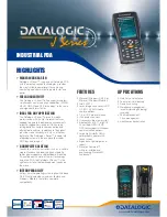
J Series
Brand: Datalogic Pages: 2
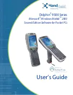
Dolphin 9500 Series
Brand: HandHeld Pages: 264
MOBILEPRO 780 -
Brand: NEC Pages: 186
NVM-DFx
Brand: NEC Pages: 8
9000
Brand: QTek Pages: 2
MOBILEPRO 770 -
Brand: NEC Pages: 2
Endurance II BND9-2
Brand: Baby Lock Pages: 60

V
Brand: Palm Pages: 8

V
Brand: Palm Pages: 8

Skorpio
Brand: Datalogic Pages: 71
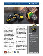
PowerScan PM8300
Brand: Datalogic Pages: 2
Falcon X4
Brand: Datalogic Pages: 2
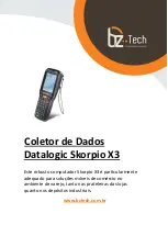
Skorpio X3
Brand: Datalogic Pages: 3
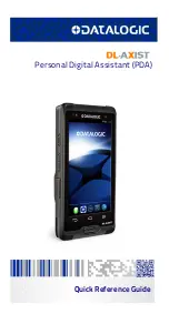
DL-Axist
Brand: Datalogic Pages: 52
Falcon X4
Brand: Datalogic Pages: 2
PA500
Brand: Unitech Pages: 123
NOMAD
Brand: TDS Pages: 38
M3 BLACK
Brand: M3 Mobile Pages: 12


