Bosch Telex Ascend, Manual
The Bosch Telex Ascend manual is a comprehensive guide that provides step-by-step instructions on how to use and optimize its advanced features. This must-have manual is available for free download at manualshive.com, ensuring easy access to all users seeking to learn more about this innovative product.
Share
Download


Reviews:
No comments
Related manuals for Telex Ascend
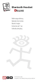
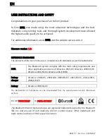
DELUXE
Brand: 2GO Pages: 20
B901
Brand: N-Com Pages: 33
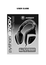
6700V
Brand: Python Pages: 8
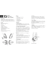
BH100
Brand: Xqisit Pages: 16
BT400
Brand: Able Planet Pages: 2
Mini
Brand: 2GO Pages: 12
Touch
Brand: Hama Pages: 27
Ellipse
Brand: Jabra Pages: 12
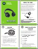
S805 - -QSG-EMEA
Brand: Motorola Pages: 6
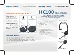
HC100
Brand: Sangoma Pages: 2
ONE
Brand: XBOX Pages: 13
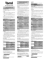
H9
Brand: Ibml Pages: 2
Steel
Brand: Jabra Pages: 20
KX-TGA106M - Cordless Extension Handset
Brand: Panasonic Pages: 6
RP-HTX80B
Brand: Panasonic Pages: 2
WXCH2050 - WIRELESS ORDER TAKER
Brand: Panasonic Pages: 12

BT160
Brand: Jabra Pages: 2
BT160
Brand: Jabra Pages: 2


