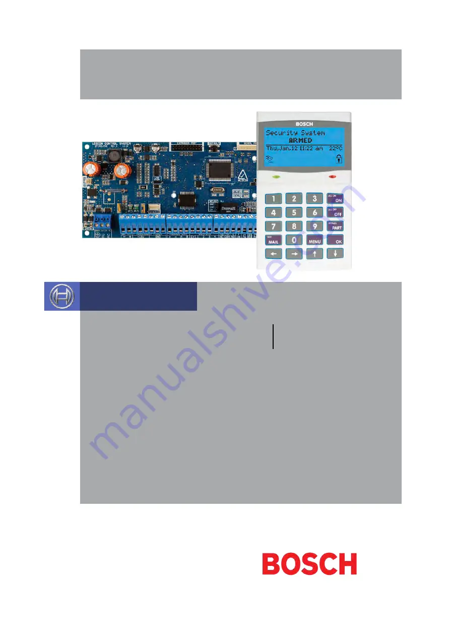
Bosch SOLUTION 6000, Installation Manual
The Bosch SOLUTION 6000 is a top-of-the-line security system designed to provide comprehensive protection for your home or business. Ensure a hassle-free installation with the step-by-step guidance provided in the free Installation Manual. Download it now from manualshive.com and take control of your security.
Share
Download


Reviews:
No comments
Related manuals for SOLUTION 6000
GL300
Brand: Lagostina Pages: 13
169132
Brand: GE Pages: 8
Encore
Brand: Baratza Pages: 2
Encore
Brand: Baratza Pages: 24
Encore
Brand: Baratza Pages: 10
V60
Brand: HARRIO Pages: 12
Maestro
Brand: Baratza Pages: 6
CS
Brand: Fama Pages: 12
Vario
Brand: Mahlkönig Pages: 52
Vario W+
Brand: Baratza Pages: 2
SETTE 30
Brand: Baratza Pages: 6
sette 270
Brand: Baratza Pages: 5
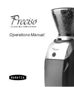
Preciso
Brand: Baratza Pages: 16
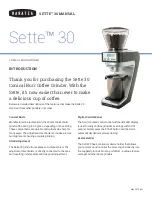
SETTE 30
Brand: Baratza Pages: 12
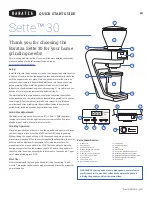
SETTE 30
Brand: Baratza Pages: 24
Maestro Plus
Brand: Baratza Pages: 15
sette 270
Brand: Baratza Pages: 21
ASTRO
Brand: La Spaziale Pages: 16


