Bosch RT30A, Instruction Manual
The Philips RT30A, an innovative device, guarantees unmatched performance. With the comprehensive Instructions For Use Manual, users can effortlessly set up and operate the product with ease. Download the user manual for free at manualshive.com, ensuring you make the most of your Philips RT30A experience.
Share
Download


Reviews:
No comments
Related manuals for RT30A

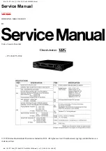
PV-V464S
Brand: Panasonic Pages: 4

PV-V4624S
Brand: Panasonic Pages: 4

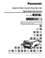
AJ-D960
Brand: Panasonic Pages: 124
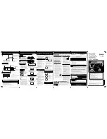
AJ-D455
Brand: Panasonic Pages: 24
PV-V4524S
Brand: Panasonic Pages: 4
NV-P05REE
Brand: Panasonic Pages: 11
OmniVision PV-QV200
Brand: Panasonic Pages: 34
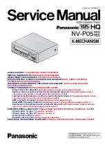
NV-P05REE
Brand: Panasonic Pages: 52
AJ-YA120AG
Brand: Panasonic Pages: 56
Omnivision PV-9661
Brand: Panasonic Pages: 407

NV-HD630 series
Brand: Panasonic Pages: 112

Omnivision PV-V4523S
Brand: Panasonic Pages: 4

Omnivision VHS PV-V4022
Brand: Panasonic Pages: 4

AG710P - VCR/BRC
Brand: Panasonic Pages: 20

NV-SJ230A
Brand: Panasonic Pages: 22

AJ-HD3700H
Brand: Panasonic Pages: 22

Omnivision PV-HD1000
Brand: Panasonic Pages: 48

NV-L20A
Brand: Panasonic Pages: 35


