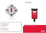
background image

Assembly instructions

3 842 358 814/2017-01

Replaces: 2016-10

ENGLISH

LU 2

Automatic lubrication unit

3 842 543 482

3 842 543 483

3 842 543 484

3 842 543 485

3 842 543 486

3 842 543 487

EN

GLISH

358814_2017_01_EN.indd   1

16.01.2017   13:38:18

Summary of Contents for Rexroth LU 2

Page 1: ...Assembly instructions 3 842 358 814 2017 01 Replaces 2016 10 ENGLISH LU 2 Automatic lubrication unit 3 842 543 482 3 842 543 483 3 842 543 484 3 842 543 485 3 842 543 486 3 842 543 487 ENGLISH ...

Page 2: ...onibles en los idiomas indicados Hay más idiomas a petición Las instrucciones están disponibles como versión impresa print o como archivo PDF media para descargar del archivo de medios www boschrexroth com mediadirectory En el buscador en la parte superior derecha donde pone Search introduzca 3 842 358 814 a continuación haga clic en fSearch PT BR Este manual de montagem está disponível nos idioma...

Page 3: ...cation unit LU 2 use 11 5 1 2 Automatic lubrication unit LU 2 design 11 5 2 Product description 12 5 3 Identification of the product 13 6 Function 14 6 1 TIME mode 14 6 1 1 Setting the delivery volume in the TIME operating mode 15 6 1 2 Display of the remaining delivery period 16 6 2 PULSE mode 17 6 2 1 Setting the delivery volume in the PULSE operating mode 18 6 3 Required delivery volume 20 6 3 1...

Page 4: ... R 2200 36 8 5 8 Install adapter Set AS 2 R 1200 AS 2 R 2200 37 8 6 Make the electrical connection to the product 38 8 6 1 PLC programming suggestions for evaluating the signal outputs 39 9 Start up 41 9 1 First time operation 41 9 1 1 Short description commissioning 42 9 2 Re commissioning after a standstill period 42 10 Operation 43 10 1 Notices regarding operation 43 10 1 1 Wear 43 10 1 2 Steps...

Page 5: ...t damage before working with the product 1 2 Required and supplementary documentation f Only operate when you are in possession of the documentation marked with the book symbol and you have understood and observed this Table 1 Required and supplementary documentation Title Document number Document type Safety related information for staff 3 842 527 147 MTparts 3 842 529 770 Spare part list availab...

Page 6: ...g DANGER Indicates a hazardous situation which will result in death or serious injury if not avoided WARNING Indicates a hazardous situation which can result in death or serious injury if not avoided CAUTION Indicates a hazardous situation which can result in minor or moderate injury if not avoided NOTICE Damage to property The product or the environment could be damaged 1 3 2 Symbols The followin...

Page 7: ...ions in this document f Read this manual thoroughly and completely before you start working with the product f Keep these instructions accessible to all users at all times f Always include the operating instructions when transferring this product to third parties 2 2 Intended use The product is an incomplete machine This product may be used for the following for installation in a Rexroth transfer ...

Page 8: ...ensure safe use these activities may only be performed by a specialist or personnel under the direction of a specialist Specialist refers to a person who can recognize potential hazards and take appropriate safety measures due to their technical training knowledge and experience and understanding of the relevant regulations pertaining to the work being performed Qualified personnel must comply with...

Page 9: ...rm in the housing Make sure that all electrical connections are either used or covered Check the security requirements according to DIN EN 619 Start up the product only if it is installed completely Make sure that all safety equipment belonging to the product is present has been installed properly and is fully functional Do not displace bypass or disable the safety equipment Do not reach into movi...

Page 10: ...air net for long loose hair As owner or operator you are responsible for appropriate protective equipment when using the product All personal protective equipment must be intact 2 8 Owner obligations Before first use or re commissioning of a conveyor system run a risk assessment in accordance with DIN EN ISO 12100 Before initial commissioning ensure that there are no protruding or sharp edged parts...

Page 11: ...this product 5 1 Performance description 5 1 1 Automatic lubrication unit LU 2 use Lubrication of concealed running transport chains in the transfer system TS 2plus for lubrication of 1 belt section BS 2 or 1 section unit SE 2 in the drive station Exclusively for operation with 2 equal lubrication pins 5 1 2 Automatic lubrication unit LU 2 design The automatic lubrication unit LU 2 consists of the...

Page 12: ...roduct description A Lubrication unit LU 2 B Drive C Oil container LC 2 1 D Holder complete with assembly accessories E Support bracket F Connection set G Adapter Set AS 2 C 100 250 1 H Adapter Set AS 2 C 400 700 1 I Adapter Set AS 2 R 300 700 1 J Adapter Set AS 2 R 1200 2200 1 K Adapter Set AS 2 R V 1 1 Not part of the delivery please order separately ...

Page 13: ...ut this product 13 54 3 842 358 814 2017 01 MIT LU 2 Bosch Rexroth AG 5 3 Identification of the product Fig 2 Name plate B Typschild A C A Part no Order number B Designation C Design and dimensions ENGLISH ...

Page 14: ...ner LC 2 Only in TIME mode At the initial startup the drive runs for approximately 8 sec after the supply voltage is connected to prime the lubrication unit The operation then starts with the first interval time When the interval time has expired the metered volume is delivered The operating mode the entered delivery period the entered oil container LC 2 Ö LC250 and the metered volume to be deliver...

Page 15: ... PULSE flash in the display 2 Press 1x the SET button The display switches to the TIME mode TIME flashes After about 3 seconds the display switches to the selection of the oil container 3 Press SET button 1x LC60 Press SET button 2x LC120 Press SET button 3x LC250 LC 2 The selected oil container flashes in the display here LC250 After about 3 seconds the display switches to the entry of the metered l...

Page 16: ...t 5 s intervals The initial start of the operation begins about 8 s after the supply voltage with the interval time 6 1 2 Display of the remaining delivery period During operation the remaining delivery period can be shown in the display f Press and hold the SET button during operation for 1 s flashing arrow icon d in the display The display shows the remaining delivery time in hours 999hhours appe...

Page 17: ...elivery are entered via the display using the SET button If the number of remaining pulses deliveries is 100 or greater the following indicator appears in the display 99 Field in the table with a gray background The delivery is carried out once with supply voltage rising flank The supply voltage must be present at least as long enough for the delivery process to be completed min 2 minutes Before th...

Page 18: ... 0 7 357 0 8 313 0 9 278 1 0 250 1 2 208 1 4 179 1 6 156 1 8 139 2 0 125 2 2 114 2 4 104 2 6 96 2 8 89 3 0 83 3 5 71 4 0 62 4 5 56 5 0 50 5 5 45 6 0 42 6 5 38 7 0 36 7 5 33 8 0 31 8 5 29 9 0 28 9 5 26 6 2 1 Setting the delivery volume in the PULSE operating mode The operating mode the oil container used LC 2 Ö LC250 and the required delivery volume per pulse delivery are entered via the display us...

Page 19: ... metered lubricant delivery volume 4 To enter the delivery volume per pulse press the SET repeatedly The delivery volume of 0 1 9 5cm pulse can be scrolled through in the pre entered steps The delivery volume entered per pulse flashes in the display Approximately 3 seconds after the entry inactive SET button the setting mode for the delivery volume is terminated The operating mode the quantity of r...

Page 20: ...0 h 6 3 2 Flat top chain Required delivery volume for 2 3 g oil m chain every 2000 h Fig 4 1 2 20 19 18 17 16 15 14 13 12 11 10 9 8 7 6 5 4 3 2 1 11 6 1 y h x m 358 814 16 Flat top chain Required delivery volume for 2 3 g oil m chain every 2000 h x m Section length y h Distance between the discharging operations 1 Delivery volume each pulse 0 26 cm3 2 Delivery volume each pulse 0 55 cm3 x m Sectio...

Page 21: ...il m chain every 1000 h 6 3 4 Accumulation roller chain Required delivery volume for 2 3 g oil m chain every 2000 h Fig 6 1 20 19 18 17 16 15 14 13 12 11 10 9 8 7 6 5 4 3 2 1 25 10 5 15 20 0 y h x m 358 814 17 Accumulation roller chain Required delivery volume for 2 3 g oil m chain every 2000 h x m Section length y h Distance between the discharging operations 1 Delivery volume each pulse 0 26 cm3...

Page 22: ...delivery volume for 2 3 g oil m chain every 2000 h Fig 8 2 3 1 20 19 18 17 16 15 14 13 12 11 10 9 8 7 6 5 4 3 2 1 7 6 5 2 3 4 1 y h x m 358 814 18 Vplus accumulation roller chain Required delivery volume for 2 3 g oil m chain every 2000 h x m Section length y h Distance between the discharging operations 1 Delivery volume each pulse 0 26 cm3 2 Delivery volume each pulse 0 55 cm3 3 Delivery volume ...

Page 23: ...ny time f Press and hold the SET button during operation for 10 s flashing arrow icon d in the display The message PU appears in the display and the special delivery is executed The lubrication unit then returns to the preset operating mode The PURGE special delivery can be canceled at any time by pressing the SET button a second time 358 814 38 ENGLISH ...

Page 24: ...ors the counter pressure of the lubrication point If the lubrication unit LU 2 detects counter pressure 6 4x in a row a resting phase will follow Recovery In this resting period the lubrication unit will try to deliver 3x each with an interval of 16 hours If the counter pressure reduces during these three deliveries 48 h the missed deliveries are automatically rescheduled at half the interval time...

Page 25: ...lt drive Flashing red Er Oil container LC 2 empty Flashing red L C Special delivery PURGE Flashing green in 1 s intervals PU Counter pressure too high p 6 bar Flashing red 0L Low temperature t 20 C Flashing red ut Backup battery drive empty L o 6 8 2 Signal outputs In addition the lubrication unit LU 2 has signal outputs OK and Err These outputs can be evaluated by a connected controller to monito...

Page 26: ...ipping documents for product weight f Make sure the carrying straps are correctly fastened before raising the product f Secure the product to prevent toppling while lifting f Make sure no one except the operator is in the danger area when raising and lowering the product 7 2 Storing the product Only store the product on a flat surface Protect the product from mechanical stress Protect the product f...

Page 27: ...ning and prevents premature wear 8 2 2 Mounting with T bolts Mount the transfer systems TS 1 TS 2plus TS 2pv TS 4plus TS 5 and the chain conveyor systems VarioFlow and VarioFlow S with T head bolt and collar nut Make sure the T bolt is in the correct position when inserting and tightening in the slot The notch at the end of the bolt indicates the orientation of the T bolt f 1 T bolt insertion posi...

Page 28: ...rews PZ Pozidriv screwdriver size PZ Phillips screwdriver size gleitmo 585 K Anti Seize Lubricate Lubricate with specific grease gleitmo 585 K gleitmo 585 K www fuchs lubritech com Anti Seize Food Grade Anti Seize Loctite 8014 www henkel com weiconlock AN302 43 Please the following as thread locking and sealing means Weiconlock AN302 43 medium strength detachable www weicon de The marked parts are ...

Page 29: ...nstall the holder for the lubrication unit LU 2 Fig 9 MD 10Nm SW4 MD 10Nm SW4 MD 10Nm SW4 SW10 358 814 02 MD 10Nm B A SW4 max 45 max 45 Install the holder for the lubrication unit LU 2 f Mount the holder vertically near the drive either at a transverse connector A or below the section profile B ENGLISH ...

Page 30: ...set in the holder Fig 10 E F 358 814 20 Install support bracket and connector set in the holder 1 Pre assemble the the support bracket E and the connection set F 2 Set the support bracket and the connection in the holder 3 Connect hoses to the lubrication unit according to your application see also page 33 to 37 ...

Page 31: ...e note The oil container may only be bolted 1x 1 Place the drive B on the oil container C Please note The rim of the drive must be placed seamlessly on the top of the oil container X 2 Screw the drive union nut on the oil container by hand Please note The union nut must be able to be screwed onto the oil container so far as the arrows on the drive are completely visible Y ENGLISH ...

Page 32: ...y and the expiration date 2 Remove the oil container plug 3 Screw the lubrication unit by hand into the support bracket E 4 Close the holder D 5 Remove the protective cap 6 Connect the connection cable to the lubrication unit Please note After connecting the power cable and with supply voltage present the LED indicators flash green GN in 5 s intervals A flashing arrow icon d appears in the display T...

Page 33: ... Different lubricating pins cause unequal distribution through an uneven flow resistance The difference in length of the lubrication lines should be 20 mm Different lubricating line lengths cause unequal lubrication distribution through an uneven flow resistance The lubrication line must always be placed lower than the lubricating pin otherwise the lubrication line runs empty uncontrolled oil spilla...

Page 34: ...ote Only use 2 equal lubricant pins do not mix adapter sets Different lubricating pins cause unequal distribution through an uneven flow resistance The difference in length of the lubrication lines should be 20 mm Different lubricating line lengths cause unequal lubrication distribution through an uneven flow resistance The lubrication line must always be placed lower than the lubricating pin otherw...

Page 35: ...r sets Different lubricating pins cause unequal distribution through an uneven flow resistance The difference in length of the lubrication lines should be 20 mm Different lubricating line lengths cause unequal lubrication distribution through an uneven flow resistance The lubrication line must always be placed lower than the lubricating pin otherwise the lubrication line runs empty uncontrolled oil ...

Page 36: ... note Only use 2 equal lubricant pins do not mix adapter sets Different lubricating pins cause unequal distribution through an uneven flow resistance The difference in length of the lubrication lines should be 20 mm Different lubricating line lengths cause unequal lubrication distribution through an uneven flow resistance The lubrication line must always be placed lower than the lubricating pin othe...

Page 37: ... the side cover of the drive head Please note Only use 2 equal lubricant pins do not mix adapter sets Different lubricating pins cause unequal distribution through an uneven flow resistance The difference in length of the lubrication lines should be 20 mm Different lubricating line lengths cause unequal lubrication distribution through an uneven flow resistance The lubrication line must always be pl...

Page 38: ... connection requires basic mechanical and electrical knowledge f The product may only be operated by qualified personnel see page 8 f The voltage supply must comply with the connection data of the lubrication unit see Technical data on page 52 Choose control and sensor elements in accordance with EN ISO 13849 Observe VDE specification VDE 0100 in Germany or the appropriate specifications in the count...

Page 39: ...o output signals A PLC terminal strip Inputs B PLC terminal strip Outputs l1 Cable white output OK l2 Cable black output Err l3 Cable brown voltage supply B05 No signal green B06 No signal red B08 Cable break 1 When using B02 l3 Fault indication only when the lubrication unit is powered 2 B01 B09 and B11 optional error display only necessary when saving Q2 Output Q2 High if Fault Oil container emp...

Page 40: ...15 PLC programming suggestion with three output signals A PLC terminal strip Inputs B PLC terminal strip Outputs l1 Cable white output OK l2 Cable black output Err l3 Cable brown voltage supply B05 No signal green B06 No signal red B08 Cable break 1 Connect output B04 directly to the input B13 if B11 B12 is not to be used 2 When using B13 l3 Fault indication only when the lubrication unit is power...

Page 41: ...l malfunctions caused by unequal distribution of the lubricant The product can be damaged the service life may be adversely affected f Only use 2 equal lubricant pins do not mix adapter sets Different lubricating pins cause unequal distribution through an uneven flow resistance f The difference in length of the lubrication lines should be 20 mm Different lubricating line lengths cause unequal distr...

Page 42: ...ly be inspected and adjusted once all required safeguards are in place Note EN ISO 13857 when you remove or replace safeguards and or nullify a safety guideline Test runs with open panels are only allowed if they are carried out by a competent person using tip switches and no interference through other switching elements exists Only start up the product if all safety devices have been installed in...

Page 43: ...sures will reduce wear Switch off the conveyor line when at standstill e g during breaks at night at weekends Do not select a higher speed for the conveyor line than that required for the corresponding function Avoid contamination due to abrasive media reduce contamination by cleaning on a regular basis 10 1 3 Environmental influences Resistant to many conventional substances used in the manufactur...

Page 44: ... work f Secure the system against being switched on unintentionally High pneumatic pressure Risk of serious injury or death f Switch off the compressed air supply on the relevant system component before performing any maintenance or repair work f All pneumatic cylinders must be depressurized vented f Secure the system against being switched on unintentionally CAUTION Hot surfaces of the electric m...

Page 45: ...re of the toothed belt Applying grease dissolving substances to the toothed belt e g when cleaning leads to the failure of the toothed belt There is a risk of damage to property f Keep degreasers or aggressive cleaning away from the toothed belt f Clean the product only with a damp cloth 11 2 Inspection Periodically check the system status for possible errors by visual inspection of the LED indica...

Page 46: ... oil container is empty and must be replaced 1 Remove the connection cable from the lubrication unit Please note Only in pulse mode After re establishing the supply voltage a delivery process is carried out 2 Open the holder D 3 Unscrew the entire lubrication unit out of the support bracket E 4 Loosen the union nut and remove the drive B from the empty oil container C 5 Dispose of the empty oil co...

Page 47: ...ainer LC 2 in support bracket see page 32 Please note After connecting the power cable and with supply voltage present the LED indicators flash green GN in 5 s intervals A flashing arrow icon appears d in the display The lubricating unit is ready for operation with the parameters previously set Please note Only in pulse mode After re establishing the supply voltage a delivery process is carried out ...

Page 48: ...red the battery is empty and must be replaced 1 Remove the connection cable A from the lubrication unit 2 Loosen the union nut and remove the drive B from the oil container C 3 Open and remove the battery compartment D 1 No scope of delivery simultaneous loosening of the two locking mechanisms with any tool e g welding wire paperclip or 2 pens 4 Remove the control board E 5 Exchange the battery CR...

Page 49: ...Secure the system against being switched on unintentionally Lifted loads may fall Falling objects can result in serious injury or even death f Always use lifting equipment with sufficient load bearing capacity see shipping documents for product weight f Check if the carrying straps are attached properly before lifting the product f The product must always be prevented from tipping over when lifting...

Page 50: ...n of materials and dismantling capacity Careless disposal may pollute the environment Dispose of the product in accordance with the currently applicable national regulations in your country 15 Upgrading and modification Do not modify the product The Bosch Rexroth warranty only applies to the system as delivered and with approved upgrades The manufacturer accepts no warranty claims for systems with ...

Page 51: ...press SET key for 1 s LED indicator flashing red Display ut Ambient temperature is too low ta 20 C Increase ambient temperature ta 20 C Clear error message press SET key for 1 s LED indicator flashing red Display LC Oil container empty Replace oil container see chapter 11 4 1 Exchange oil container LC 2 on page 46 Control device setting LED indicator flashing red Display LC Oil container not empty In...

Page 52: ...om 50 to 60 C Protection class IP65 Acoustic emission 70 dB A Weight LU 2 with oil container LC 2 approx 740 g Capacity oil container LC 2 250 cm Connection cable M8 x 1 according to IEC 61076 2 104 halogen free length 5 m 10 m Outer sheath material PUR black Conductor cross section 4 x 0 25 mm Bending radius 44 mm min 17 1 Storage period Storage period drive connection cable max 2 years oil conta...

Page 53: ...ld fungus rodents and other vermin Installation and operation in the immediate vicinity of industrial equipment with chemical emissions is not permitted Do not install or operate near sources of sand or dust Do not install and operate in areas which are regularly jarred by high forces caused by for example presses or heavy machinery Resistant to many common media used in production such as water m...

Page 54: ...Bosch Rexroth AG PO Box 300207 70442 Stuttgart Germany Fax 49 711 811 7777 info boschrexroth de www boschrexroth com Subject to modifications 3 842 358 814 2017 01 ...

Reviews: