

ctrlX I/O
Analog Input Terminal
4-channel, 0 to 10 V, 16 Bit, Bipolar
DOK-XIO***-XI312204*AI-DA01-EN-P
R911418823
Edition 01
R911418823, Edition 01, 1 / 8
1
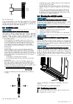
XI312204
The analog input terminal XI312204 processes signals in the
range from 0 to 10 V in a ctrlX I/O station. The input signal
is digitized with a resolution of 16 bits and transferred galvan-
ically isolated to the system level. The 4 input channels are
differential inputs. Error states are shown at the channel LED
on the removable peripheral connector and routed to the con-
trol via the local bus.
The logic and peripheral voltage supply as well as the
EtherCAT-based module communication are routed through
the module.
For the integration into the parent system, the respective ESI
files are available. For the ESI files, go to
chrexroth.com/electrics.
Ensure that the current documentation is consulted.
For the current documentations, go to
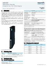
Fig. 1: Module XI312204
2
Ordering data
Type
Part number Description
XI312204
R911406105 Analog input module, voltage
between 0 and 10 V
For more ordering data (accessories), go to the product cat-
alog under
www.boschrexroth.com/electrics.
3
Technical data
3.1 General technical data
XI312204
Number of inputs
4
Connection method Push-in
XI312204
Connection method 2-wire, shielded, twisted in pairs
Signal type
Differential
Input signal
0 V to 10 V
Input resistance
>250 k
Ω
Limit frequency of
input filter
12.8 kHz
Conversion time
100
μ
s
Resolution D/A
16 bits incl. sign
Accuracy
Typ.
±
0.1 % of the end value of the
measured range (MBE)
Max.
±
0.3% of MBE
Overload protection No, DC 30 V max.
Common Mode
Max.
±
35 V compared to U
P
GND
Voltage supply
U
P
via jumper contacts
Current consumption
U
L
40 mA
Current consumption
U
P
21 mA
Bit width, input data
in the process data
image
(including filling bit)
18 bytes in the standard representation
12 bytes in the "compact" representa-
tion
Can be set channel-granularly
Parameterization
Via ctrlX Works (start parameter)
Configuration
No address or configuration setting
required
Dimensions
12 mm × 105 mm × 99 mm (width ×
height × depth)
Weight
95 g (module including connector)
Electrical isolation
DC 1200 V U
P
to U
L
, DC 707 V U
P
/U
L
to
FE
EMC resistance
Acc. to EN 61000-6-2 and EN 61000-6-4
Mounting position
Vertical, on a horizontal support rail
Labeling, approvals
CE, UKCA
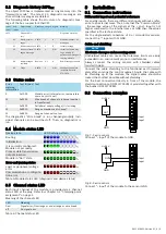
3.2 Clamping point assignment
Clamping
point
Signal
LED
Pusher
1
AI Kanal 1+
Red
Grey
2
AI Kanal 1-
None
Grey
3
AI Kanal 2+
Red
Grey
4
AI Kanal 2-
None
Grey
5
AI Kanal 3+
Red
Grey
6
AI Kanal 3-
None
Grey
7
AI Kanal 4+
Red
Grey
8
AI Kanal 4-
None
Grey


