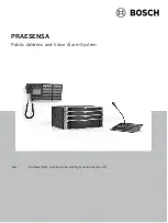
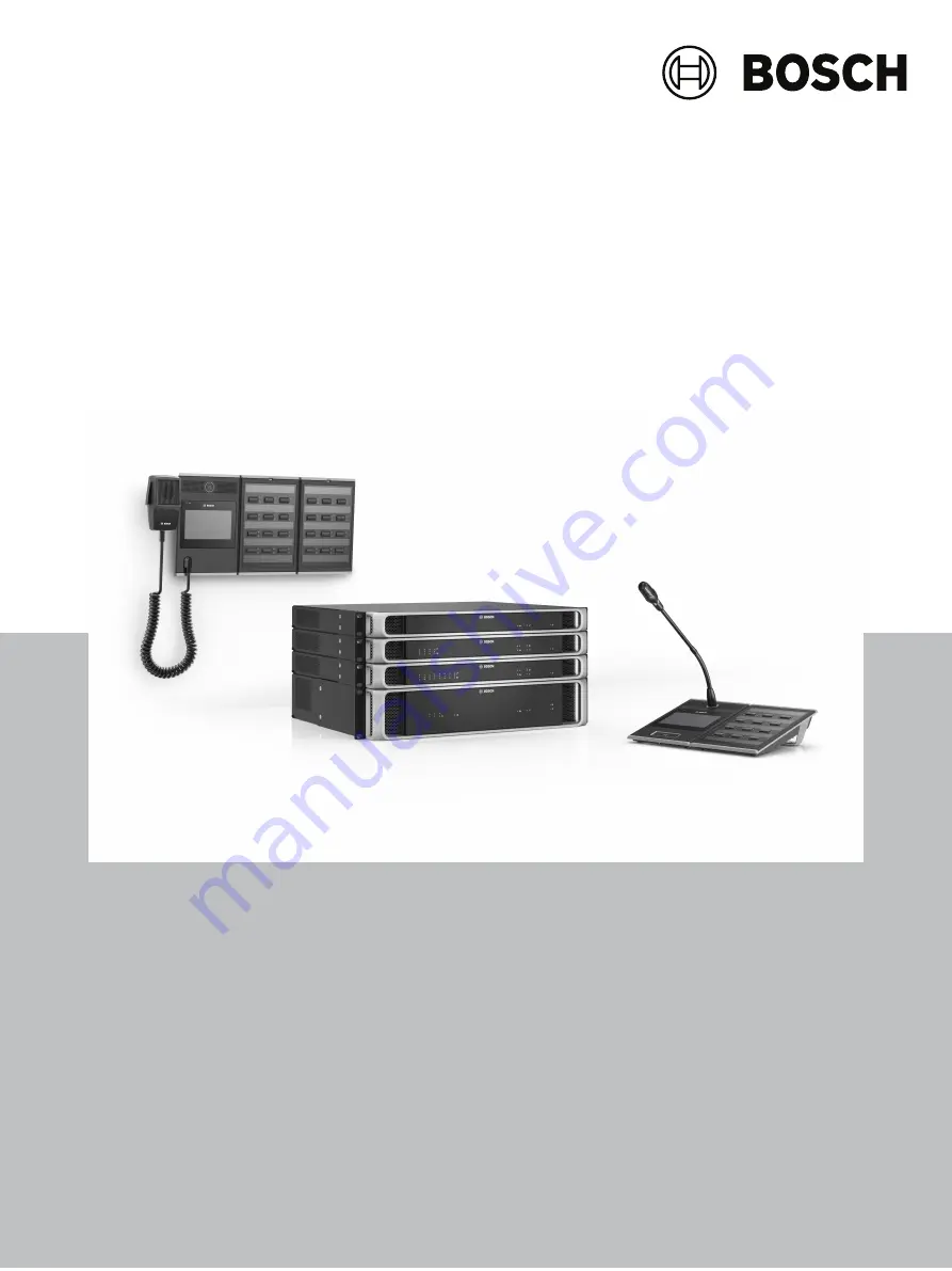
background image

PRAESENSA

Public Address and Voice Alarm System

en

Underwriters Laboratories Listing Document (ULLD)

Summary of Contents for PRAESENSA

Page 1: ...PRAESENSA Public Address and Voice Alarm System en Underwriters Laboratories Listing Document ULLD ...

Page 2: ......

Page 3: ...abinets 16 3 1 3 Mounting the 19 rack devices 17 3 1 4 Field wire cable requirements 19 3 1 5 Security and data protection 23 3 2 Battery calculation 24 3 2 1 Topology 24 3 2 2 Operating conditions 24 3 2 3 Power consumption 26 3 2 4 Accurate battery size calculation 26 3 3 System controller PRA SCL PRA SCM PRA SCS 28 3 3 1 Connections 28 3 3 2 Functional diagram 29 3 3 3 Parts included 29 3 3 4 P...

Page 4: ...e 73 3 7 8 System controller power supply 74 3 7 9 Power over Ethernet 75 3 7 10 Ethernet network 76 3 7 11 Control inputs 78 3 7 12 Control outputs 79 3 7 13 Technical data 80 3 8 LCD call station PRA CSLD PRA CSLW 83 3 8 1 Connections 83 3 8 2 Functional diagram 84 3 8 3 Parts included 85 3 8 4 Interconnection call station extension 85 3 8 5 Power over Ethernet 86 3 8 6 Line input 87 3 8 7 Techn...

Page 5: ...ller PRA SCL 124 5 1 1 Functions 124 5 2 Amplifier 600W 4 8 channel PRA AD604 PRA AD608 124 5 2 1 Functions 124 5 3 End of line device PRA EOL US 125 5 3 1 Functions 125 5 4 Multifunction power supply large PRA MPS3 125 5 4 1 Functions 125 5 5 LCD call station PRA CSLD PRA CSLW 126 5 5 1 Functions 126 5 6 Call station extension PRA CSE 127 5 6 1 Functions 127 5 7 Ethernet switch PRA ES8P2S 127 5 7...

Page 6: ...142 8 Compatibilities 143 8 1 NAC Appliances 143 8 2 Loudspeakers 143 8 3 FACP and Annunciators 144 9 System Configuration 145 9 1 System with ACU 146 9 2 System with ACU and LOC 148 9 3 Multi building system 151 9 4 Interconnection with B9512G or B8512G panel 153 9 5 Interconnection with B9512G or B8512G panel with amber and clear strobes 155 9 6 Generic interfacing with fire panel 157 10 System ...

Page 7: ...nel FACP with remote notification capability can provide early warning of a developing fire Such a system however does not assure protection against property damage or loss of life resulting from a fire An emergency communication system typically made up of an automatic fire alarm system as described above and a life safety communication system that may include an autonomous control unit ACU local...

Page 8: ... life safety system malfunction is inadequate maintenance To keep the entire life safety system in excellent working order ongoing maintenance is required per the manufacturer s recommendations and UL and NFPA standards At a minimum the requirements of NFPA 72 shall be followed Environments with large amounts of dust dirt or high air velocity require more frequent maintenance A maintenance agreeme...

Page 9: ...rinted circuit board location Do not tighten screw terminals more than 9 in lbs Over tightening may damage threads resulting in reduced terminal contact pressure and difficulty with screw terminal removal This system contains static sensitive components Always ground yourself with a proper wrist strap before handling any circuits so that static charges are removed from the body Use static suppress...

Page 10: ... a specific application UL 2572 compliant software version s Release date Released version Reason 2021 12 1 42 Official release 1 5 Standards PRAESENSA complies with the following standards Certification Standard Underwriters Laboratories UL UL2572 for Mass Notification Installations Standard for Control Units and Accessories for Fire Alarm Systems UL864 10th Edition FCC Part 15 Class A PRAESENSA ...

Page 11: ... been certified to comply with the requirements in the UL 2572 standard for Mass Notification Installations Product Description PRA SCL System controller large PRA SCM System controller medium PRA SCS System controller small PRA AD604 Amplifier 600W 4 channel PRA AD608 Amplifier 600W 8 channel PRA EOL US End of line device PRA MPS3 Multifunction power supply large PRA CSLD Desktop LCD call station...

Page 12: ... of the trademark owner with no intention of infringement of the trademark 1 11 Notice of liability While every effort has been taken to ensure the accuracy of this document neither Bosch Security Systems nor any of its official representatives shall have any liability to any person or entity with respect to any liability loss or damage caused or alleged to be caused directly or indirectly by the ...

Page 13: ...ion Reason 2021 12 14 V0 14 Section updated 1 4 1 12 2 3 1 2 3 1 3 3 1 4 3 2 3 3 6 1 3 7 13 3 10 1 3 12 3 12 5 3 12 6 3 12 8 6 4 2 6 4 4 6 4 5 6 4 6 6 4 7 6 4 8 8 1 9 1 9 2 9 3 9 4 9 5 9 6 11 2021 12 15 V0 15 Section updated 1 12 6 4 2 6 4 3 6 4 4 6 4 5 6 4 7 6 4 8 2021 12 16 V0 15a Section updated 1 4 1 7 1 12 2021 12 21 V0 15b Section updated 1 5 1 12 3 12 3 ...

Page 14: ...l signaling and BGM applications PRA AD604 Amplifier 600W 4 channel Power partitioning across four channels Supplying output power to loudspeakers channels PRA AD608 Amplifier 600W 8 channel Power partitioning across eight channels Supplying output power to loudspeakers channels PRA EOL US End of line device Loudspeaker end of line supervision Fault detection in amplifier PRA MPS3 Multifunction po...

Page 15: ...E Call station extension Loudspeaker zone and actions selection Used in combination with PRA CSLD and PRA CSLW PRA ES8P2S Ethernet switch 10 port Ethernet switch with PoE and SFP PRA SFPSX PRA SFPLX Fiber transceivers SX For multi mode fibers covering distances up to 550 m LX For single mode fibers covering distances up to 10 km PRA FRP1 US PRA FRP2 US PRA FRP3 US First responder panel USA 1 exten...

Page 16: ...ring including that to the non fire alarm equipment shall be installed in accordance with the requirements of the National Fire Alarm and Signaling Code NFPA 72 Access level All PRAESENSA devices must be installed at a physical security level 1 according to the UL2572 by means of installation in a lockable rack as described in Mounting the 19 rack devices page 17 or in the lockable housing of the ...

Page 17: ...ntrol level 1 See First responder panel PRA FRPx US PRA FRPx USNY page 108 End of Line board The End of Line board PRA EOL US must be installed in a UL listed junction box to ensure Physical Access level 1 See Mounting page 58 3 1 3 Mounting the 19 rack devices Only use UL50 listed Lowell 19 racks and make sure that each rack is of suitable quality to support the weight of the devices Only UL list...

Page 18: ... Installation wiring PRAESENSA 2021 12 21 V0 15b F 01U 402 882 Underwriters Laboratories Listing Document ULLD Bosch Security Systems B V Mounting brackets are used to mount the device in 19 equipment racks ...

Page 19: ...or to installation Confirm the following The cable selected is proper for the application taking into account all applicable local state provincial and national codes The cable has not been damaged in transit or storage During cable installation The following factors must be considered Do not exceed the fill capacity of raceways and cable trays Use grommets to protect cables when passing through m...

Page 20: ...20 en Installation wiring PRAESENSA 2021 12 21 V0 15b F 01U 402 882 Underwriters Laboratories Listing Document ULLD Bosch Security Systems B V ...

Page 21: ...lad aluminum CCA wires are cheaper but have a higher resistance than copper for the same diameter When using CCA cables take the next bigger wire size from the table Examples A 150 W loudspeaker load on a loudspeaker line of 480 m in a 100 V system Round up to table values 200 W and 500 m This requires 1 5 mm2 copper wires or 2 5 mm2 CCA wires A 150 W loudspeaker load on a 1200 ft loudspeaker line...

Page 22: ...le and termination quality and the environment in which the cable is used In case of doubt use a cable checker to see whether the cable conforms to CAT5e TIA EIA 568 B Ethernet glass fiber cable Use single mode or multi mode glass fiber that fits the SFP transceiver Take the maximum cable length and attenuation into account Product Glass fiber Max attenuation Max length PRA SFPLX Single mode 10 5 ...

Page 23: ...82 3 1 5 Security and data protection PRAESENSA is suitable for Communication Security level 1 PRAESENSA supports Access Security Level 2 when at least eight characters are used as passwords and when the configuration software Automatic logout after inactivity of 30 minutes or less is configured under system options System options page 136 ...

Page 24: ...m the 24 VDC output of the PRA MPS3 Only the number of active Ethernet ports increases the power consumption PRA CSLD PRA CSLW PRA CSE The power consumption of the PRA CSLD and PRA CSLW is the same Again the power consumption consists of a fixed part with an increment per active Ethernet port Power is supplied via PoE to one or both ports Power is taken from the port that has the highest PoE volta...

Page 25: ... the PRA MPS3 to switch on the 48 VDC power supply again and the amplifier will operate from the normal supply voltage The power consumption of the active amplifier will then vary between the value for low power small signal audio or small loudspeaker load and full power audio in full load at maximum level In all modes the power consumption of the active Ethernet ports must be taken into account B...

Page 26: ...full power per active RJ45 port 6 0 8 9 56 77 246 0 4 6 0 9 5 68 93 271 0 4 0 50 0 79 5 67 7 75 22 58 0 03 PRA ES8P2S Ethernet switch per active RJ45 port per active SFP port PoE load 7 0 0 4 0 7 load 8 4 0 5 0 8 1 2 x load 0 70 0 04 0 07 0 1 x load PRA MPS3 Multifunction power supply per active RJ45 port per active SFP port 5 2 0 4 0 7 5 2 0 4 0 7 0 43 0 03 0 06 PRA FRP3 US First responder panel ...

Page 27: ...e idle Amplifier active low power Amplifier active full power per active RJ45 port 2 0 50 0 67 3 83 5 25 20 33 2 x 0 03 24 24 0 5 0 5 16 08 10 17 1 47 PRA AD608 Amplifier sleep Amplifier snooze Amplifier active idle Amplifier active low power Amplifier active full power per active RJ45 port 2 0 50 0 79 5 50 7 50 22 58 2 x 0 03 24 24 0 5 0 5 18 96 11 29 1 47 PRA AD608 Amplifier sleep Amplifier snoo...

Page 28: ...igure 3 1 Rear view connections Rear panel connections Chassis ground 24 to 48 VDC input A B 24 48 V Memory card Network port 1 5 1 Field connections Connection Field wiring Circuit class Ilimited IMax minimum AWG Remarks Chassis ground 24 to 48 VDC input A B NO Class 2 power limited Wiring 30 14 AWG Network port 1 5 NO Class 2 power limited Class N Must stay within same room 20 ft and within meta...

Page 29: ...and tone storage Controller OMNEO network switch 3 3 3 Parts included The box contains the following parts Quantity Component 1 System controller 1 Set of 19 rack mounting brackets pre mounted 1 Set of screw connectors and cables 1 Quick Installation Guide 1 Safety information No tools SD card or Ethernet cables are provided with the device Parts check and identification x2 x2 B C x8 D A System co...

Page 30: ...iable electrical connection Use a dedicated crimping tool 2 Insert each wire into the appropriate slot of the connector B observing polarity Wiring color convention red for and black for Use a flat blade screwdriver to tighten each connection 3 Insert the cable into the 24 to 48 V input A cut the cable to length and mount the connector of the powering device to the other end of the cable again obs...

Page 31: ...ay realization to enable the use of multiple connections simultaneously for cable redundancy e g to daisy chain devices in a loop with a maximum of 21 devices in a loop 3 Port assignments For general purpose Public Address systems all ports 1 5 can be used The PRAESENSA system controller can be set up to work on two completely separate networks simultaneously for fail over redundancy supporting Da...

Page 32: ...nternal storage Call events Fault events General events 1000 1000 1000 Message tone storage capacity Mono uncompressed 48 kHz 16 bit 90 min System size Networked devices Zones 150 System controller 500 Power transfer Power supply input A B Input voltage range 24 VDC Power consumption 24 V 300 mA Network interface Ethernet Protocol Redundancy 100BASE TX 1000BASE T TCP IP RSTP Ports 5 Environmental ...

Page 33: ...isting Document ULLD 2021 12 21 V0 15b F 01U 402 882 Mechanical Enclosure Dimensions WxHxD With mounting brackets Rack unit 483 x 44 x 400 mm 19 x 1 75 x 15 7 in 19 in 1U Case Material Color Steel RAL9017 Frame Material Color Zamak RAL9022HR Mounting position Horizontal Weight 5 8 kg 12 8 lb ...

Page 34: ... Field wiring Circuit class Ilimited IMax minimum AWG Remarks Safety ground 48 VDC input A B 1 3 NO Class 1 not power limited 7 A Wiring max 28 12 AWG Lifeline control audio supply interface 1 3 to amplifier 1 3 NO Class 1 not power limited Loudspeaker output A B 1 4 YES Class 1 not power limited 14 A Wiring Class A or Class B Wiring max 28 12 AWG End of line device NO Class 1 not power limited 14...

Page 35: ...A B 2 1 DC to DC converter Audio processing DSP OMNEO network switch Controller Lifeline control interface Lifeline supply input Lifeline audio input 1 4 Amplifier channel Spare channel 3 4 3 Parts included The box contains the following parts Quantity Component 1 Amplifier 600W 4 channel 1 Set of 19 rack mounting brackets pre mounted 1 Set of screw connectors and cables 1 Quick Installation Guide...

Page 36: ...n be used for a wire connection to the rack frame The rack frame must be grounded to safety ground This is a conductive path to ground or earth that is designed to protect persons from electrical shock by shunting away any dangerous currents that might occur due to malfunction or accident Use a thick multi strand wire 2 5 mm2 with wire eyelets and washers for a solid connection The safety ground c...

Page 37: ... dedicated crimping tool 2 Insert each wire into the appropriate slot of the connector B observing polarity Wiring color convention red for and black for Use a flat blade screwdriver to tighten each connection 3 Insert the cable into the 48 V input A cut the cable to length and mount the connector of the powering device to the other end of the cable again observing polarity Insert this connector i...

Page 38: ...mption during mains absent Required for UL2572 compliancy G E E MPSx C 123456 To create a lifeline connection follow the procedure below 1 Crimp ferrules E onto the ends of the electrical wires of cable G to provide a solid and reliable electrical connection Use a dedicated crimping tool 2 Insert each wire into the appropriate slot of the connector C The wiring order is not critical but use the sa...

Page 39: ...ponse This combination of features makes it possible to partition the available amplifier power across all channels and utilize that power effectively Every channel has a 6 pole connector socket providing independently switched loudspeaker group A and group B outputs and a separate connection facility for an End of Line device for loudspeaker cable supervision The two outputs can be used for singl...

Page 40: ...the connected loudspeaker power the length of cable and the maximum permissible attenuation of the acoustic sound level due to loudspeaker line losses See also section Field wire cable requirements page 19 for loudspeaker cable size recommendations 2 Insert the near end wires of the loudspeaker cable into slots 1 and 2 of connector D preferably using crimped on wire ferrules that fit to the wire g...

Page 41: ...half of the loudspeakers in parallel in a loop through fashion to output A Observe polarity Follow the same wiring procedure as for using a single line 2 Connect an end of line device to the end of loudspeaker line A 3 Repeat this procedure for the other half of the loudspeakers and connect them to output B 4 Connect an end of line device to the end of loudspeaker line B Loudspeaker lines A and B ...

Page 42: ...side of the loudspeaker cable to output B In this case maintaining the correct polarity is especially important as reversal on one end will short circuit the amplifier channel not immediately but when output B is activated in case of interruption of one conductor 3 Connect an end of line device to the end of line connection terminals These terminals are connected in parallel to output B internally...

Page 43: ...with RJ45 connectors to connect the amplifier to the network 2 Connect one end of the cable to one port of the amplifier 3 Connect the other side of the cable to another network port in the network This can be one port of the system controller a port of a separate switch in the network but also a port of another PRAESENSA device in the same rack 4 The second port of the amplifier can be connected ...

Page 44: ... ohm 70 V mode load 46 7 ohm Other channels 100 V mode load 133 3 ohm 70 V mode load 66 7 ohm 150 W 150 W 150 W 105 W 75 W 75 W Power transfer Power supply input A B Input voltage 48 VDC Maximum current consumption 7A Supervision End of Line detection mode Pilot tone 25 5 kHz 3 VRMS Power supply input A B Undervoltage Ground short detection loudspeaker lines 50 kohm Amplifier channel redundancy sw...

Page 45: ... Operating Storage and transport 5 to 50 C 23 to 122 F 30 to 70 C 22 to 158 F Humidity non condensing 5 to 95 Airflow Fan airflow Front to sides rear Mechanical Enclosure Dimensions WxHxD With mounting brackets Rack unit 483 x 44 x 400 mm 19 x 1 75 x 15 7 in 19 in 1U Case Material Color Steel RAL9017 Frame Material Color Zamak RAL9022HR Mounting position Horizontal Weight 8 1 kg 17 9 lb ...

Page 46: ... 8 Network port 1 2 1 Field connections Connection Field wiring Circuit class Ilimited IMax minimum AWG Remarks Safety ground 48 VDC input A B 1 3 NO Class 1 not power limited 7 A Wiring max 28 12 AWG Lifeline control audio supply interface 1 3 to amplifier 1 3 NO Class 1 not power limited Loudspeaker output A B 1 8 YES Class 1 not power limited 14 A Wiring Class A or Class B Wiring max 28 12 AWG ...

Page 47: ...1 2 3 4 5 6 7 8 A B 2 1 DC to DC converter Audio processing DSP OMNEO network switch Controller Lifeline control interface Lifeline supply input Lifeline audio input 1 8 Amplifier channel Spare channel 3 5 3 Parts included The box contains the following parts Quantity Component 1 Amplifier 600W 8 channel 1 Set of 19 rack mounting brackets pre mounted 1 Set of screw connectors and cables 1 Quick In...

Page 48: ... of high internal voltages All PRAESENSA 19 devices have a chassis ground screw on the rear panel which can be used for a wire connection to the rack frame The rack frame must be grounded to safety ground This is a conductive path to ground or earth that is designed to protect persons from electrical shock by shunting away any dangerous currents that might occur due to malfunction or accident Use ...

Page 49: ...rimp ferrules H onto the ends of the electrical wires of cable F to provide a solid and reliable electrical connection Use a dedicated crimping tool 2 Insert each wire into the appropriate slot of the connector B observing polarity Wiring color convention red for and black for Use a flat blade screwdriver to tighten each connection 3 Insert the cable into the 48 V input A cut the cable to length a...

Page 50: ...er consumption during mains absent Required for UL2572 compliancy MPSx To create a lifeline connection follow the procedure below 1 Crimp ferrules E onto the ends of the electrical wires of cable G to provide a solid and reliable electrical connection Use a dedicated crimping tool 2 Insert each wire into the appropriate slot of the connector C The wiring order is not critical but use the same orde...

Page 51: ... all channels and utilize that power effectively Every channel has a 4 pole connector socket providing independently switched loudspeaker group A and group B outputs The two outputs can be used for single Class A single Class B or dual Class B field wiring Caution Amplifier outputs may carry output voltages up to 100 VRMS Touching uninsulated terminals or wiring may result in an unpleasant sensati...

Page 52: ...tion 3 For loudspeaker line supervision make sure that all loudspeakers are connected in a loop through fashion and that an end of line device is connected to the end of the loudspeaker line for supervision No cable spurs or branches are allowed because they will not be supervised Dual Class B wiring A B EOL US Figure 3 8 Dual Class B wiring If loudspeaker line redundancy is needed then follow the...

Page 53: ... the procedure below to connect the loudspeakers according to this scheme 1 Connect all loudspeaker in parallel in a loop through fashion Observe equal polarity for all loudspeakers Connect one side of the loudspeaker cable to output A observing polarity 2 Connect the other side of the loudspeaker cable to output B In this case maintaining the correct polarity is especially important as reversal o...

Page 54: ...with RJ45 connectors to connect the amplifier to the network 2 Connect one end of the cable to one port of the amplifier 3 Connect the other side of the cable to another network port in the network This can be one port of the system controller a port of a separate switch in the network but also a port of another PRAESENSA device in the same rack 4 The second port of the amplifier can be connected ...

Page 55: ...el 1 100 V mode load 66 7 ohm 70 V mode load 46 7 ohm Other channels 100 V mode load 133 3 ohm 70 V mode load 66 7 ohm 150 W 150 W 150 W 105 W 75 W 75 W Power transfer Power supply input A B Input voltage 48 VDC Maximum current consumption 7A Supervision End of Line detection mode Pilot tone 25 5 kHz 3 VRMS Power supply input A B Undervoltage Ground short detection loudspeaker lines 50 kohm Amplif...

Page 56: ...ic conditions Temperature Operating Storage and transport 5 to 50 C 23 to 122 F 30 to 70 C 22 to 158 F Humidity non condensing 5 to 95 Airflow Fan airflow Front to sides rear Mechanical Enclosure Dimensions WxHxD With mounting brackets Rack unit 483 x 44 x 400 mm 19 x 1 75 x 15 7 in 19 in 1U Case Material Color Steel RAL9017 Frame Material Color Zamak RAL9022HR Mounting position Horizontal Weight ...

Page 57: ...nnections Device connections Loudspeaker line Field connections Connection Field wiring Circuit class Ilimited IMax minimum AWG Remarks Loudspeaker line YES Class 1 Not power limited 14 A Wiring Class A and Class B Wiring max 26 14 AWG 3 6 2 Functional diagram Functional and connection diagram Internal device functions Loudspeaker line Bandpass filter Supervision receiver transmitter ...

Page 58: ...6 4 Mounting The PRA EOL US must be mounted in a UL listed junctions box with a minimum size of 4 x 4 or in the Lowell 19 rack when connected for Class A wiring close to the PRA AD60x amplifier i Notice When selecting cables and wire gauge for loudspeaker connections take into account the length and loudspeaker load to avoid excessive power loss Make sure that the signal level at the end of the lo...

Page 59: ...d junctions box mounting hole as indicated 3 Add the washer and nut to the bottom side of the screw and junctions box Tighten the nut with a maximum force of 0 7 Nm until the EOL device fits correctly in place WARNING tighten with too much force could damage the EOL board 4 Pull wiring cables into junctions box through the selected knockout location Secure conduit wiring cable etc to junctions box...

Page 60: ...ting plate of the end of line device can be broken off 1 and snapped in place as bottom plate 2 3 2 From the bottom side of the shelf put two mounting screws through the shelf mounting holes and the EOL board holes as indicated 3 Add two nuts to the top side of the screws and EOL board and tighten Tighten the nuts with a maximum force of 0 7 Nm until the EOL device fits correctly in place WARNING ...

Page 61: ...on wiring en 61 Bosch Security Systems B V Underwriters Laboratories Listing Document ULLD 2021 12 21 V0 15b F 01U 402 882 5 Connect the wiring to the EOL devices and route the wiring to the amplifier s See Wiring page 62 ...

Page 62: ...ut branches The end of line device is then connected to the last loudspeaker using the supplied connection wire To do so 1 Cut the wires 1 to the required length for connection to the end of line device feeding the wires through the strain relief slot 2 in the housing The end of line device uses a 2 pole push wire connector The stripped wire ends must be inserted into the connector completely up t...

Page 63: ...e 1000 m 80 nF 20 to 50 C 4 to 122 F Maximum input voltage 100 VRMS This product is intended for dry indoor use only Environmental Climatic conditions Temperature Operating Storage and transport 5 to 50 C 23 to 122 F 30 to 70 C 22 to 158 F Humidity non condensing 5 to 95 Mechanical Enclosure Dimensions WxHxD Board shape Box shape 78 x 60 x 16 mm 3 1 x 2 4 x 0 6 in 45 x 60 x 18 mm 1 8 x 2 4 x 0 7 i...

Page 64: ...3 3 7 1 Connections Figure 3 10 Rear view connections Chassis ground Mains input with fuse Battery 12 VDC CF8 100A Battery temperature sensor 48 VDC output A B 1 3 to amplifier 1 3 5 5A Lifeline control audio supply interface 1 3 to amplifier 1 3 24 VDC output A B to system controller Control input 1 8 1 Control output 1 8 1 Network port 1 5 port 1 and 2 with PoE 1 Network port 6 SFP 6 ...

Page 65: ...1 not power limited 48 VDC output A B 1 3 to amplifier 1 3 NO Class 1 not power limited 7 A Wiring 28 12 AWG Lifeline control audio supply interface 1 3 to amplifier 1 3 NO Class 1 not power limited 24 VDC output A B to system controller NO Class 2 power limited Wiring 30 14 AWG Control input 1 8 NO Class 2 power limited Control output 1 8 NO Class 2 power limited Network port 1 2 with PoE YES Cla...

Page 66: ...ssing DSP Mains to DC converter DC to DC converter Battery charger Control input processor Control output relay Lifeline audio output Lifeline supply output Lifeline control interface Diode Fuse 3 7 3 Parts included The box contains the following parts Quantity Component 1 Multifunction power supply 1 Set of 19 rack mounting brackets pre mounted 1 Set of screw connectors 1 Battery connection set w...

Page 67: ...ery side see chapter below immediately at the positive battery terminal Alternatively the fuse can be mounted at the power supply side see chapter below when local standards require so Never use two fuses one on each side because this would increase the series resistance of the cable assembly and the high peak currents of a system in emergency mode would result in voltage dips that could limit the...

Page 68: ...s Mat refers to a specific type of SLA or VRLA and can be used also Caution 1 The battery must be electrically floating Never connect any battery terminal to ground The battery terminals must be wired individually to the battery connection terminals of the PRA MPS3 2 A battery may not be connected to more than one PRA MPS3 this means that it cannot be shared by multiple power supplies i Notice 1 T...

Page 69: ...connection terminal using the other M8 self locking nut K Tighten with torque 5 Nm 3 Insert the connector of the battery temperature sensor assembly J into the temperature sensor connector socket of the power supply 4 Connect the open end of the black cable O to the negative battery terminal with the eyelet of the temperature sensor J on top Depending on the type of battery and its terminals use a...

Page 70: ...n M8 self locking nut K Tighten with torque 5 Nm When the black O and red N battery cables are fixed to each other make sure that the isolated fuse eyelet on the red cable N is at the power supply side otherwise reverse the complete cable set 2 Put the fuse M on the long positive battery connection terminal of the power supply followed by the isolated eyelet of the red cable N with the metal side ...

Page 71: ...hed 3 7 5 Mains power connection 1 Check that the mains AC power supply meets the nominal input rating of the PRA MPS3 2 Use the supplied power cord I to connect to the mains line The PRA MPS3 has no power switch Plug unit into a permanent power outlet inside the rack enclosure i Notice The power cord with a plug can be used to disconnect the PRA MPS3 from the mains Connect the plug to an easily a...

Page 72: ...x 1 2 3 5 5 5 5 5 5 Connection procedure 1 The power supply interconnection wiring and ferrules are delivered with the amplifier The power supply terminal plugs B are delivered with the multifunction power supply 2 Follow the power supply cable assembly instructions as provided for the amplifiers Observe polarity 3 Insert the power supply terminal plugs of the interconnection cables into the A B s...

Page 73: ...cy C AD60x 1 2 3 123456 To complete the lifeline interconnection follow the procedure below 1 The 6 pole cable and connector for the amplifier are delivered with the amplifier For lifeline assembly instructions refer to the following amplifier sections Lifeline page 38 and or Lifeline page 50 2 The 6 pole connector C for the multifunction power supply is delivered with the power supply 3 Mount the...

Page 74: ...use both connections D SCx 5 5 5 5 Connection procedure 1 The power supply interconnection wiring and ferrules are delivered with the system controller The power supply terminal plugs D are delivered with the multifunction power supply 2 Follow the power supply cable assembly instructions as provided for the system controller Observe polarity 3 Insert the power supply terminal plugs D of the inter...

Page 75: ...AESENSA call station has two Ethernet ports and can be connected with two cables for fail safe cable redundancy It is also possible to connect a call station to two separate multifunction power supplies for additional protection against failure of its Ethernet switch Ports 3 to 5 cannot be used for PoE powering CSLx 5 5 5 5 PoE devices can simply be connected using Gb Ethernet cables with RJ45 con...

Page 76: ... it can be discovered by the system controller to make it part of the system 2 The other ports can be used for a loop through connection to a next device Devices can just be daisy chained or be connected in a loop in which case the system can recover from a broken link 3 The availability of a multi port switch makes the multifunction power supply an ideal device for decentralized system clusters t...

Page 77: ...Document ULLD 2021 12 21 V0 15b F 01U 402 882 PRA SFPSX 550 m PRA SFPLX 10 km 1 2 PRA SFPxX 5 5 5 5 Caution Risk of eye injury When inspecting a connector ensure that light sources are off The light source in fiber optic cables may cause eye injury SX and LX fiber connections use invisible IR light ...

Page 78: ...er system for activation E 12 1 8 Connection procedure 1 Use a 2 wire cable proper for the installation and the 16 pole terminal plug E delivered with the device 2 Insert the near end wires of the cable into the appropriate slots of terminal plug E preferably using crimped on wire ferrules that fit to the wire gauge used Use a flat blade screw driver to tighten each connection 3 Connect the other ...

Page 79: ...nfigured independently for various actions Make sure not to exceed the maximum contact rating Refer to the Control output contact rating graphic below F 1 4 5 8 2 3 456 5 5 5 5 Connection procedure 1 Use a 2 wire or 3 wire cable proper for the installation and application and one of the 12 pole terminal plugs delivered with the device 2 Insert the near end wires of the cable into the appropriate s...

Page 80: ...8 8 A 13 5 V Regulated 24 VDC output Nominal DC output voltage Maximum continuous current Maximum peak current 24 V 0 7 A 0 9 A Power over Ethernet PoE 1 2 Nominal DC output voltage Standard Maximum PD load 48 V IEE 802 3af mode B 12 95 W Power consumption Mains powered Active mode all outputs loaded Battery powered Active mode all outputs loaded 1000 W 1000 W Control interface Control input conta...

Page 81: ...rotocol Redundancy 100BASE TX 1000BASE T TCP IP RSTP Class N Ports RJ45 SFP 5 2 with PoE 1 This product is intended for dry indoor use only Environmental Climatic conditions Temperature Operating Storage and transport 5 to 50 C 23 to 122 F 30 to 70 C 22 to 158 F Humidity non condensing 5 to 95 Airflow Fan airflow Front to sides rear Mechanical Enclosure Dimensions WxHxD With mounting brackets Rack...

Page 82: ...82 en Installation wiring PRAESENSA 2021 12 21 V0 15b F 01U 402 882 Underwriters Laboratories Listing Document ULLD Bosch Security Systems B V Enclosure Weight 11 8 kg 26 lb Mounting position Horizontal ...

Page 83: ...writers Laboratories Listing Document ULLD 2021 12 21 V0 15b F 01U 402 882 3 8 LCD call station PRA CSLD PRA CSLW PRA CSLD PRA CSLW 3 8 1 Connections Figure 3 11 Bottom view wiring connections Network port 1 2 PoE PD Local source audio line input PRA CSE interconnection ...

Page 84: ...ine input NO Class 2 power limited PRA CSE interconnection NO Class 2 power limited Enclosure Must stay within same room 20 ft and within metal conduit 3 8 2 Functional diagram Functional and connection diagram Internal device functions Fixed microphone on a flexible stem Internal monitor loudspeaker Audio processing DSP Power over Ethernet OMNEO network switch Controller Press To Talk button PRA ...

Page 85: ...afety information No tools or Ethernet cables are provided with the device Parts check and identification A Desktop wallmount LCD call station A1 Hand held microphone clip A2 Microphone clip connection screws 3 8 4 Interconnection call station extension Add up to four PRA CSE call station extensions for zone selection and other functions Without extensions the call station can only be used with a ...

Page 86: ...orts 1 and 2 or a PRA ES8P2S Ethernet switch ports 1 8 In case one of the connections fail or one of the PSE sources fail the operation of the call station is not affected With both connections to the same PSE there is still connection redundancy but no PSE redundancy The ports of the call station can be looped through to another PRAESENSA device but at least one port must be connected to a PSE to...

Page 87: ...input is not supervised unplugging the cable to the audio player will not be reported as a fault i Notice When music is played from a PC that is connected to a grounded mains supply there is a risk of hum being inserted into the music input of the call station This is caused by unequal ground potentials of the different mains supplies Use a cable with integrated transformers for ground loop isolat...

Page 88: ...se cancelling Display Size 4 3 Touch screen Capacitive Color depth 24 bit Resolution 480 x 272 px Brightness 300 cd m2 Monitor loudspeaker Maximum sound pressure level at 1 m 75 dBSPL Volume control Mute 40 dB to 0 dB Power transfer Power over Ethernet PoE 1 2 Nominal DC input voltage Standard 48 V IEEE 802 3af mode B Maximum input current 350 mA IEEE802 3af With 0 to 4 PRA CSE connected Rated vol...

Page 89: ...ace Ethernet Protocol Redundancy 100BASE TX 1000BASE T TCP IP RSTP Ports 2 This product is intended for dry indoor use only Environmental Climatic conditions Temperature Operating Storage and transport 5 to 50 C 23 to 122 F 30 to 70 C 22 to 158 F Humidity non condensing 5 to 95 Mechanical Enclosure PRA CSLD Dimensions HxWxD Excluding microphone 62 x 130 x 189 mm 2 44 x 5 12 x 7 44 in Ingress prote...

Page 90: ...h Security Systems B V Enclosure PRA CSLW Dimensions HxWxD 62 x 130 x 189 mm 2 44 x 5 12 x 7 44 in Ingress protection IP30 Base Material Color Zamak RAL9017 Panel Material Color Plastic RAL9017 RAL9022HR Weight 1 0 kg 2 21 lb Mounting position In any angle from Horizontal to Vertical with the display facing up or forward ...

Page 91: ...nsion PRA CSE 3 9 1 Connections Figure 3 12 Bottom view wiring connections Connection to next extension RJ12 Connection to call station or previous extension RJ12 Field connections Connection Field wiring Circuit class Ilimited IMax minimum AWG Remarks Interconnection RJ12 NO Class 2 power limited Enclosure Must stay within same room 20 ft and within metal conduit ...

Page 92: ...t indicator 3 9 3 Parts included The box contains the following parts Quantity Component 1 Call station extension 1 Bracket attached to bottom 1 Metal coupling plate 4 screws 1 RJ12 interconnection cable 1 Button cap x3 1 Quick Installation Guide 1 Safety information No tools or Ethernet cables are provided with the device Parts check and identification B Call station extension B1 Patch cable B2 C...

Page 93: ...station and the extension using a TX10 screwdriver For the call station get access to the two screws via the holes in the table stand bracket 2 Mount the coupling plate between the call station and the first extension using four M3 screws with TX10 head Mounting plate and screws are included with the extension An extension can only be mounted to a call station on its right hand side looking from a...

Page 94: ...cover plate to lift up the top cover 2 Slide the cover upwards to remove it 3 Turn the cover upside down Gently push a screwdriver of tweezers into the hole in the metal top side label holder Slide the label holder to the left to unlock and then up to remove This label holder is for the title label of the extension It is made of metal and is also used to fix the top cover magnetically to the body ...

Page 95: ...bel holder to the right to lock it in place 7 Mount the cover back on the extension body by first sliding the bottom side into the body then tilt down until it snaps into place 3 9 6 Mounting a button cap The call station extension has provisions to add a cap over one or more buttons as a safeguard against accidental activation Each PRA CSE is delivered with a set of three caps each consisting of ...

Page 96: ...ows of three around the buttons Use tweezers to lift and remove the row for the button that should get a cap 4 Remove the original light ring by cutting the plastic bridges to the adjacent light rings Leave part of the plastic bridges in place around each light ring for better orientation when it is put back in place 5 Insert one of the new light rings with pivot pins in the slot around the button...

Page 97: ...er side of the hinge for the right pivot pin Rotate the cap 10 degrees counterclockwise and slide to the right over the button so the left pivot pin goes into the hole of the hinge Then push the right side of the cap down until the right pivot pin snaps into the slot of the hinge This requires some force 9 After the cap has snapped into place the hinge has two stable positions and the cap can be f...

Page 98: ...sor Watchdog This product is intended for dry indoor use only Environmental Climatic conditions Temperature Operating Storage and transport 5 to 50 C 23 to 122 F 30 to 70 C 22 to 158 F Humidity non condensing 5 to 95 Mechanical Enclosure Dimensions HxWxD 62 x 130 x 189 mm 2 44 x 5 12 x 7 44 in Ingress protection IP30 Base Material Color Zamak RAL9017 Panel Material Color Plastic RAL9017 RAL9022HR ...

Page 99: ...nderwriters Laboratories Listing Document ULLD 2021 12 21 V0 15b F 01U 402 882 3 10 Ethernet switch PRA ES8P2S 3 10 1 Connections Front panel connections Port 1 8 Network port 1 8 with PoE Port 9 10 Network combo port 9 10 Console Console serial RS232 cable COM port ...

Page 100: ...ring Circuit class Ilimited IMax minimum AWG Remarks Chassis ground Network port 1 8 with PoE YES Class 2 power limited Class N Network combo port 9 10 YES Class 2 power limited Class N Can only be used for SPF modules for UL864 UL2572 Console serial RS232 cable COM port NO Can not be used for UL864 UL2572 48 VDC input 1 and 2 NO Class 1 not power limited Max xx xx AWG Fault relay N C Can not be u...

Page 101: ...h 1 Screw connector 2 Wall mounting bracket 1 DIN rail mounting bracket and screws 1 Startup manual No tools or Ethernet cables are provided with the device 3 10 4 Power supply connection This Ethernet switch has a dual 48 VDC input and must be powered from the PRA MPS3 to one of the 48 V outputs normally intended for the amplifiers Use both A and B outputs for connection redundancy The 48 V outpu...

Page 102: ...gether Output power per port 1 8 IEEE 802 3 af at 120 W 30 W Network interface Ethernet Speed Ports 1 8 Ports 9 10 100BASE TX 1000BASE T RJ45 RJ45 SFP combo Only SFP is allowed This product is intended for dry indoor use only Climatic conditions Temperature Operating Storage and transport 5 50 C 23 122 F 40 85 C 40 185 F Humidity non condensing 5 95 Functional Switching MAC address table size 8k M...

Page 103: ...sch Security Systems B V Underwriters Laboratories Listing Document ULLD 2021 12 21 V0 15b F 01U 402 882 Enclosure Mounting TS35 DIN Rail EN 60715 Wall mounting Case Aluminum Weight 1 3 kg 2 7 lb Mounting position Horizontal power at the top ...

Page 104: ...socket of the PRA MPSx and PRA ES8P2S The transceiver receives power from the host device PRA SFPSX 550 m PRA SFPLX 10 km 1 2 PRA SFPxX 5 5 5 5 Caution Risk of eye injury When inspecting a connector ensure that light sources are off The light source in fiber optic cables may cause eye injury SX and LX fiber connections use invisible IR light Field connections Connection Field wiring Circuit class ...

Page 105: ...all a transceiver 4 With the handle on the transceiver oriented towards the host device slide the transceiver into the SFP socket and push until it clicks into place 5 Verify that the handle on the transceiver is in the position that secures the transceiver and prevents it from being dislodged from the socket 3 11 5 Fiber cable To insert a fiber cable with LC connector follow the procedure below 1...

Page 106: ... swappable Locking Optical Interface Connector type Dual LC Wave length 850 nm Fiber length 50 µm core 550 m 1 804 ft Optical fiber Multi mode Core size 50 µm PRA SFPLX Electrical Interface Supply voltage From host device PRA MPSx or PRA ES8P2S Speed IEEE 802 3z 1000BASE LX Connection Hot swappable Locking Optical Interface Connector type Dual LC Wave length 1310 nm Fiber length 10 km 32 821 ft Op...

Page 107: ...021 12 21 V0 15b F 01U 402 882 Climatic conditions Temperature Operating Storage and transport 5 50 C 23 122 F 40 85 C 40 185 F Humidity non condensing 5 95 Mounting position Inside the Host PRA MPS3 or PRA ES8P2S Mechanical Enclosure Dimensions HxWxD 13 4 x 8 5 x 56 5 mm 0 53 x 0 33 x 2 2 in Weight 75 g 0 17 lbs ...

Page 108: ...RA CSLW and three call station extensions PRA CSE In case of loss a key code 1358 for the PRA FRPx US can be ordered at Bosch with ordering code D102 There are three New York versions of the First responder panels that have a specific lock on the door The versions are PRA FRP1 USNY PRA FRP2 USNY and PRA FRP3 USNY In case of loss a key for the PRA FRPx USNY can be ordered at a local distributor wit...

Page 109: ... CSE 3 Network port 1 2 PoE PD PRA CSE interconnection 3 Field connections Connection Field wiring Circuit class Ilimited IMax minimum AWG Remarks Network port 1 2 located on PRA CSLW YES Class 2 power limited Wiring Class N PRA CSE interconnection 3 NO Class 2 power limited Internal connections to the PRA CSLW and other PRA CSE on the First responder panel are prewired at the factory Enclosure Mu...

Page 110: ...l monitor loudspeaker sounder Audio processing DSP Power over Ethernet OMNEO network switch Controller Zone status indicator Zone trouble indicator 3 12 3 Parts included The box contains the following parts Quantity Component 1 First responder panel 1 Key 4 Screws with screw covers 1 Trim rim 1 Operating instructions 1 Safety information 3 12 4 Installation instructions The First responder panel i...

Page 111: ... of the enclosure approximately 5 feet above the floor with the hinge located on the left Precise mounting location is subject to emergency response plan and local AHJ approval Knockouts are provided at the top back and bottom of the enclosure for wiring convenience Conductors Determine the number of conductors required to be installed Select and remove the appropriate knockouts prior to mounting ...

Page 112: ...mage 2 To prevent damage to the First responder panel electronics and microphone and to facilitate backbox mounting the outer plexiglass door and the chassis with electronics and microphone should be removed 3 Turn keylock key clockwise to unlock the outer plexiglass door Open door about 180 degrees Disconnect the ground strap cable at one end with terminal lug Remove the outer plexiglass glass do...

Page 113: ...led in the backbox 6 Swing chassis open disconnect ground cable then slide upward to remove 7 Place chassis assembly into a protective anti static bag and set aside 8 Remove desired knockout s top bottom back before mounting backbox to wall 9 Place the backbox onto desired mounting location against the wall Mark the upper center installation keyhole 1 located inside the enclosure at top center on ...

Page 114: ...backbox from the wall Drill 4 additional holes in the wall where marked Install additional mounting hardware in 4 holes Hang backbox on center screw install 4 remaining screws and tighten all IMPORTANT Depending on the mounting surface the correct mounting material i e screws should be used to ensure a safe and correct surface mounting 12 Pull wiring cables into backbox through selected knockout l...

Page 115: ...e outer plexiglass door Slide outer plexiglass door over hinges on left side of the backbox IMPORTANT Re install the ground cable Close door lock by turning key counter clockwise 90 degrees Remove key 3 12 6 Semi Flush mount instructions The following installation instructions apply to semi flush mounting 1 Carefully unpack the First responder panel and check for shipping damage 2 To prevent damag...

Page 116: ...B V 5 Swing chassis open Disconnect the ground strap cable at one end with terminal lug Then slide the chassis upwards to free it from the backbox Place the chassis assembly into a protective anti static bag in a safe location until it can be reinstalled in the backbox 6 Swing chassis open disconnect ground cable then slide upward to remove ...

Page 117: ...esired mounting location against the wall Confirm location of internal wall studs before cutting hole in wall Determine which stud left or right side that will be not be cut and will be used to secure one side of the enclosure to 10 Cut hole in wall of sufficient size that will allow insertion of the enclosure into the wall Cut support stud that is blocking enclosure entry Modify adjacent stud by ...

Page 118: ...box Tighten the nut with a maximum force of 0 9 Nm Allow sufficient cable length for connection to the PRA CSLW when the chassis is in the open position See Power over Ethernet connections page 119 15 Add Trim Kit Place Trim Kit onto wall Secure to wall in 4 corners using supplied mounting hardware 526 2 mm 20 72 in 519 2 mm 20 44 in 42 02 mm 1 65 in 6 27 mm 0 25 in 16 Re attach the chassis assemb...

Page 119: ...able redundancy and supply redundancy For maximum protection it is advised to connect each port to a different independent PSE such as a PRA MPS3 multifunction power supply ports 1 and 2 or a PRA ES8P2S Ethernet switch ports 1 8 In case one of the connections fail or one of the PSE sources fail the operation of the First response panel is not affected With both connections to the same PSE there is...

Page 120: ...120 en Installation wiring PRAESENSA 2021 12 21 V0 15b F 01U 402 882 Underwriters Laboratories Listing Document ULLD Bosch Security Systems B V ...

Page 121: ...that have a specific lock on the door The versions are PRA FRP1 USNY PRA FRP2 USNY and PRA FRP3 USNY In case of loss a key for the PRA FRPx USNY can be ordered at a local distributor with code 2642 NYC fire key Electrical Microphone Nominal acoustic input level configurable 85 105 dBSPL Maximum acoustic input level 120 dBSPL Signal to Noise Ratio SNR 73 dBA Directivity Unidirectional Frequency ran...

Page 122: ...1000BASE T TCP IP RSTP This product is intended for dry indoor use only Climatic conditions Temperature Operating Storage and transport 5 50 C 23 122 F 30 70 C 22 158 F Humidity non condensing 5 95 Mechanical Enclosure Dimensions WxHxD 458 x 448 x 110 mm 18 x 17 6 x 4 33 in Ingress protection IP30 Base Material Color Steel Red RAL3002 Door panel Material Color Steel Red RAL3002 Door panel plexigla...

Page 123: ...n en 123 Bosch Security Systems B V Underwriters Laboratories Listing Document ULLD 2021 12 21 V0 15b F 01U 402 882 4 Operation Local Emergency relocation paging Live Pre recorded Refer to Operating instructions page 160 ...

Page 124: ...acility on SD card for emergency audio logging and call stacking The integrated call stacker automatically forwards recorded calls to previously occupied zones Internal real time clock for scheduled events and event time stamping support for Network Time Protocol NTP with automatic adjustment for Daylight Saving Time DST Internal system event and fault event log Networked control interface for thi...

Page 125: ... zones in case both network connections or the amplifier network interface would fail 5 3 End of line device PRA EOL US 5 3 1 Functions Supervision Reliable supervision of a single loudspeaker line using loudspeakers connected in a loop through fashion Operation is based on pilot tone detection from the amplifier with feedback to the amplifier using the loudspeaker line itself No additional wiring...

Page 126: ...Functions IP network connection Direct connection to the IP network For redundant network and power connection a second Network cable should be connected Business operation Full color 4 3 capacitive touch screen with intuitive function menu navigation provides guidance and feedback during the process of live announcements pre recorded messages and music control Successful broadcast of announcement...

Page 127: ...en extensions Robust metal coupling plate All extensions are automatically addressed from left to right All assembling can be done with one standard Torx TX10 screwdriver Labeling Removable front cover for easy labeling with space for three lines of text per button Button cap Three button caps are included to prevent unintended activation of critical buttons 5 7 Ethernet switch PRA ES8P2S 5 7 1 Fu...

Page 128: ...microphone Full color 4 3 capacitive touch screen with intuitive interface Built in monitor loudspeaker with volume control 36 buttons can be configured for various functions but they are especially useful for zone selection giving a clear overview of accessible zones and the LED indicators for each button show the status of the respective zone like being selected occupied or at fault Buttons can ...

Page 129: ...ers Laboratories Listing Document ULLD 2021 12 21 V0 15b F 01U 402 882 Fault tolerance Each of the two RJ45 network connectors accept PoE to power the call station This provides fail safe network connection redundancy as one connection is sufficient for full operation ...

Page 130: ...disabled and a redundant network installed the system will not function See the PRAESENSA installation manual i Notice How to set up PRAESENSA in an Ethernet network is outside the scope of this manual To prevent network failures in both PRAESENSA and in a Ethernet network where RSTP is not supported or allowed contact your local IT representative in case PRAESENSA needs to be part of the external...

Page 131: ...me and the software release number See Mandatory software The name of and link to the system controller Configure A button that opens the configuration items selection Diagnose A button that opens the diagnostics items selection Security A button that opens the system Security and Open Interface item selection e g download certificate Print configuration A button that opens the configuration print...

Page 132: ...Notice Initially you have already created an Administrator user account See Logon the application page 130 The webserver provides the following authorization levels Administrators Administrators have access to all parts of the webserver including the User accounts part Logging Server Logging Viewer and Open Interface Installers With the exception of the User accounts and Backup and restore parts i...

Page 133: ...n Permitted in UL2572 Y N required Possible settings Value Settings permitted in UL2572 Device options System controller Yes Supervision Power supply input A Power supply input B Enable disable Set to enable Yes Network redundancy Selection Single network ports 1 5 Dual network primary ports 1 4 secondary port 5 Set to single network Yes Emergency relevant Enable disable Default set to enable Ampl...

Page 134: ...e settings Value Settings permitted in UL2572 Device options Multifunction power supply General Yes AC power supervision Enable disable Set to enable Yes Battery supervision Enable disable Set to enable Yes Emergency relevant Enable disable Set to enable Control inputs Function Yes Local BGM source Selection Ancillary function Yes Local BGM on off Selection Ancillary function Yes Local BGM volume ...

Page 135: ...Supervision Enable disable Set to enable for ACU LOC Yes Input gain Selection 10 to 10 dB Make sure speech intelligibility is sufficient Settings Extension Function Yes Make announcement Selection Allowed Yes Make announcement with zone selection Selection Allowed Yes Transfer of control Selection Select for ACU LOC Not allowed in combination with live speech announcements when multiple PRA FRP ar...

Page 136: ...col RSTP Enable disable Set to enable Yes Call station operator language Selection of language Set to English UL 2572 Yes UL amplifier mode Enable Disable Set to enable Emergency mode Yes Disable calls below priority level Selection prio 0 224 Set to 224 Backup power mode Yes Disable calls below priority level Selection prio 0 255 Ancillary function Yes Report mains supply fault Enable disable Set...

Page 137: ...2572 Y N required Possible settings Value Settings permitted in UL2572 Call definitions Configuring definition of announcements calls Call definitions Yes Priority Selection 32 255 224 for emergency use Other values for Ancillary function Required Alarm Selection None Emergency Set for Emergency in case priority is 224 Yes Start tone Selection A start tone fit for the intended purpose Yes Attenuat...

Page 138: ...y is sufficient Yes Continue call Selection No After interruption Set to After interruption for emergency use Yes Audio input Selection Default input An audio input for the intended source Select Default for ACU LOC use 6 4 7 Action definitions On the Action definitions pages specific device functionality can be configured e g the buttons of the call station extension control inputs of the multifu...

Page 139: ...y for ACU LOC Extension Acknowledge and or reset Yes Operation Type Ack reset Do once Trouble Emergency Trouble and Emergency Acknowledge Reset Ack and Reset See Select an operation type and Ackn reset fitting to the intended use For Types Emergency and Emergency and Trouble the option Reset aborts active emergency appears with No as the only option This Ack and Reset of the Emergency state and tr...

Page 140: ...rity Below the Security page secured system connections can be viewed and or defined Topic Configure programming Feature or option Permitted in UL2572 Y N required Possible settings Value Settings permitted in UL2572 Security System security Required User name Enter characters 5 32 5 32 characters Required Passphrase Enter characters 8 64 8 64 characters ...

Page 141: ...e the system if needed Use the Diagnose section of the configuration webpages to Check the amplifier load conditions for any changes compared to the previous measurement A new load measurement will result in audible test tones in the zones under test Preferably do the measurement when the zones are not occupied or announce upcoming tests to the occupants Check the battery impedance of all connecte...

Page 142: ...eplacement of the part Test of the associated functions Fuse replacement The following fuse in the PRA MPS3 can be replaced during maintenance by a qualified technician Mains inlet T10 AH 250 V 5x20 mm 12 V battery connector Little fuse CF 58V 100A Supply and charger board F200 250 V 5 A 5x20 mm MPS3 charger board 18 V to control board F100 F101 125 V 5 A SMD Slo Blo MPS3 charger board to charger ...

Page 143: ...x Altronix X X RE2R battery box red version Altronix X X i Notice Where NAC circuits needs to be synchronized these NACs must be installed in the same or adjacent racks 8 2 Loudspeakers Model Manufacturer UL864 UL2572 LC1 UM06E8 with LC1 MFD Bosch X X LC1 UM12E8 with LC1 MFD Bosch X X LHM0606 00 US with LBC3080 01 Bosch X X LC4 UC06E with LC4 MFD Bosch X X LC4 UC12E with LC4 MFD Bosch X X LC4 UC24...

Page 144: ... Systems B V 8 3 FACP and Annunciators Model Manufacturer UL864 UL2572 B8512G B926M Bosch X X B9512G B926M Bosch X X B8512G B926F Bosch X B9512G B926F Bosch X FPD 7024 Bosch X Notification appliances cannot be connected to the B8512G B9512G or FPD 7024 Compatible NAC appliances need to be used to connect notification appliances ...

Page 145: ...ystem 3 PRA AD604 Amplifier 600W 4 channel O or PRA AD608 O Per system 150 of PRA SCL and PRA FRPx US PRA AD608 Amplifier 600W 8 channel O or PRA AD604 O PRA MPS3 Multifunction power supply large M 1 PRA CSLD Desktop LCD call station O 0 PRA CSLW Wallmount LCD call station O 0 PRA FRPx US First responder panel USA 3 extensions M 1 Per system 20 PRA EOL US End of line device M 1 Per amplifier outpu...

Page 146: ... extensions Make emergency announcement call Selection of zones and actions First responder panel PRA FRPx US PRA FRPx USNY page 108 1 PRA AD608 Amplifier 600W 8 channel Provides audio signals up to 8 loudspeaker channels zones Amplifier 600W 8 channel PRA AD608 page 46 1 PRA MPS3 Multifunction power supply large Main power supply source for the PRAESENSA system devices Multifunction power supply ...

Page 147: ...r power supply page 72 Power supply page 49 Lifeline interface 1 3 to amplifier 1 3 Lifeline page 73 Lifeline page 50 General network port Ethernet network page 54 Ethernet network page 76 Ethernet network page 31 Loudspeaker output Amplifier outputs page 51 Mains input Mains power connection page 71 Battery 12 VDC Battery and fuse page 67 24 VDC output A B to system controller System controller p...

Page 148: ...3 PRA AD608 Amplifier 600W 8 channel Can provide audio signals up to 8 loudspeaker channels zones Amplifier 600W 8 channel PRA AD608 page 46 2 PRA MPS3 Multifunction power supply large Main power supply source for the PRAESENSA system devices Multifunction power supply large PRA MPS3 page 64 1 PRA SCL System controller large Controlling the system and functions System controller PRA SCL PRA SCM PR...

Page 149: ...rt 1 2 with PoE Power over Ethernet page 75 48 VDC output A B 1 3 to amplifier 1 3 Amplifier power supply page 72 Power supply page 49 Lifeline interface 1 3 to amplifier 1 3 Lifeline page 73 Lifeline page 50 General network port Ethernet network page 54 Ethernet network page 76 Ethernet network page 31 Loudspeaker output Amplifier outputs page 51 Mains input Mains power connection page 71 Battery...

Page 150: ...02 882 Underwriters Laboratories Listing Document ULLD Bosch Security Systems B V 24 VDC output A B to system controller System controller power supply page 74 Power supply page 30 Control input 1 8 Control inputs page 78 Control output 1 8 Control outputs page 79 ...

Page 151: ...oudspeaker channels zones Amplifier 600W 8 channel PRA AD608 page 46 2 PRA MPS3 Multifunction power supply large Main power supply source for the PRAESENSA system devices Multifunction power supply large PRA MPS3 page 64 2 PRA SCL System controller large Controlling the system and functions System controller PRA SCL PRA SCM PRA SCS page 28 2 PRA ES8P2S Ethernet switch Ethernet switch PRA ES8P2S pa...

Page 152: ...r power supply page 72 Power supply page 49 Lifeline interface 1 3 to amplifier 1 3 Lifeline page 73 Lifeline page 50 General network port Ethernet network page 54 Ethernet network page 76 Ethernet network page 31 Loudspeaker output Amplifier outputs page 51 Mains input Mains power connection page 71 Battery 12 VDC Battery and fuse page 67 24 VDC output A B to system controller System controller p...

Page 153: ...strobe but can be used for second strobe zone 4 8 input Expansion Module B208 D Notification input and output signal wiring for clear strobe 5 Control panel B9512G or B8512G E Also for clear strobe but can be used for second strobe zone 6 8 input Expansion Module B208 F SDI2 class b wiring 7 Octo output module B308 G Connect the following output contact triggers from the PRAESENSA output contacts ...

Page 154: ...age 51 I Ethernet PoE Class N wiring See First responder panel PRA FRPx US PRA FRPx USNY page 108 11 Items 13 and 14 must be mounted side by side Possible at multiple locations 12 Remote Annunciator B926M 13 LOC ACU First responder panel PRA FP3 US See First responder panel PRA FRPx US PRA FRPx USNY page 108 i Notice When connecting input notification devices to the B9512G or B8512G panel it is im...

Page 155: ...r fire strobes R1002ULADA D Notification output signal wiring for MNS strobe 4 NAC rack for MNS strobes R1002ULADA E Notification input and output signal wiring for fire strobe 5 8 input Expansion Module B208 F Notification input and output signal wiring for MNS strobe 6 7 Notification appliance module D192G G SDI2 class b wiring 8 8 input Expansion Module B208 H Connect the following output conta...

Page 156: ... 108 11 Octo output module B308 13 PRAESENSA system See i e PRAESENSA product overview page 14 14 Loudspeaker zones See i e Amplifier outputs page 39 and Amplifier outputs page 51 15 Items 16 and 17 must be mounted side by side 16 Remote Annunciator 17 LOC ACU First responder panel PRA FRP3 US See First responder panel PRA FRPx US PRA FRPx USNY page 108 i Notice When connecting input notification ...

Page 157: ...nput contact module addressable C Interconnection wiring 4 FACP Fire Alarm Control Panel D Class b SLC wiring 5 Isolator if required E Class b SLC wiring 6 FACP input contact module addressable F Class b SLC wiring 7 FACP output contact module addressable relays G Max 8 Input contact wiring e g Fire system fire trigger trouble battery AC etc See Control outputs page 79 8 PRAESENSA system See i e P...

Page 158: ...ponder panel PRA FRPx US PRA FRPx USNY page 108 i Notice Items 4 and 13 must be mounted next to each other if no fire annunciator is available or if the control of the fire system is available on the FACP or if there are no control buttons Silence Reset on the fire annunciator i Notice The FACP item 4 and NAC item 2 need to be able to support 15 minutes Alarm after 24 h of standby This is required...

Page 159: ...mic OMNEO channels 8 Audio inputs static Dante or AES67 channels 120 Audio outputs static Dante channels 8 Frequency range 100 Hz to 20 kHz Control Maximum number of PRAESENSA devices 150 Maximum number of zones 500 Maximum Ethernet subnets 1 Ethernet Loop size 21 Network interface Ethernet Protocol Redundancy 100BASE TX 1000BASE T TCP IP RSTP Audio control protocol Network audio latency Audio dat...

Page 160: ...and placed adjacent to the First responder panel for ready reference Local Service Representative Name Address Phone This First responder panel interface is a full function LOC or ACU The First responder panel has a display and a sounder that emits distinct condition tones to alert you to alarm or trouble events as they occur In conjunction with the display and sounder status indicators provide th...

Page 161: ...responder panel can be operated To Request Control Press Request Control To Deny Control Press blinking Deny Control button To Grant Control Press blinking Grant Control button At ACU Control can be forced by pressing and holding the button related to the Control Indicator for two seconds 8 Unlock Annunciator press and hold Within five seconds of pressing the button the annunciator will be unlocke...

Page 162: ...e FACP will indicate the source and type of alarm Acknowledging and silencing the alarm must also be done through the FACP Trouble Operation When a trouble condition occurs such as wiring for a Loudspeaker line is cut or AC power fails the First responder panel sounder activates briefly approximately every 5 seconds The Trouble indicator lights on the display the trouble log shows the active troub...

Page 163: ...PRAESENSA Operating instructions 163 Bosch Security Systems B V Underwriters Laboratories Listing Document ULLD 2021 12 21 V0 15b F 01U 402 882 ...

Page 164: ...164 Operating instructions PRAESENSA 2021 12 21 V0 15b F 01U 402 882 Underwriters Laboratories Listing Document ULLD Bosch Security Systems B V ...

Page 165: ......

Page 166: ...Bosch Security Systems B V Torenallee 49 5617 BA Eindhoven Netherlands www boschsecurity com Bosch Security Systems B V 2021 202112211354 Building solutions for a better life ...

Reviews: