Bosch MIC 612 Series, Installation Manual
The Bosch MIC 612 Series product is a rugged, high-performance surveillance camera designed for demanding outdoor environments. For easy installation and setup, users can download the comprehensive Installation Manual from our website, completely free of charge.
Share
Download


Reviews:
No comments
Related manuals for MIC 612 Series

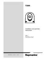
T300
Brand: Raymarine Pages: 38

DC-TH Series
Brand: Idis Pages: 14
DTI 1/19
Brand: Zeiss Pages: 88
HM-TD2H37T-10/X
Brand: Hikmicro Pages: 9
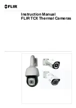
TCX series
Brand: FLIR Pages: 150
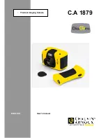
C.A 1879
Brand: Chauvin Arnoux Pages: 22
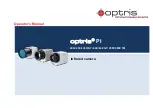
PI 640
Brand: optris Pages: 92

HM-TS03-15XF
Brand: Hikmicro Pages: 159
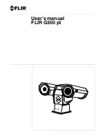
G300 pt Series
Brand: FLIR Pages: 80
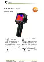
testo 868s
Brand: ICS Schneider Messtechnik Pages: 42
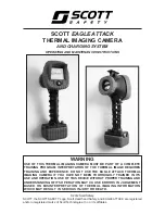
Eagle Attack
Brand: Scott Pages: 36
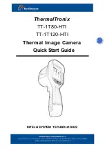
ThermalTronix TT-1T80-HTI
Brand: Intellisystem Pages: 5
E70110
Brand: Raymarine Pages: 47
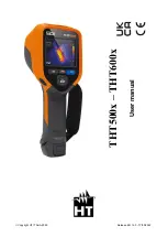
THT500 Series
Brand: HT Pages: 54
TE-SQ1
Brand: i3system Pages: 8
ThermaCAM PM575
Brand: FLIR Pages: 68
FLIR Ex Series
Brand: DATATEC Pages: 41
MD 9910
Brand: METREL Pages: 17


