background image

Plena Universal Pre-amplifier

Installation and Operating Manual

LBB 1920

en

Summary of Contents for LBB 1920

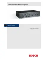
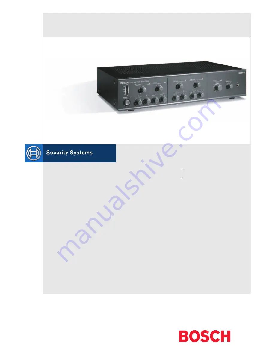
Page 1: ...Plena Universal Pre amplifier Installation and Operating Manual LBB 1920 en ...

Page 2: ......

Page 3: ... the plug still fails to fit contact your electrician to replace your obsolete outlet Do not defeat the safety purpose of the polarised plug Alternatively this unit may be equipped with a 3 wire grounding type plug having a third grounding pin This plug will only fit into a grounding type power outlet This is a safety feature If you are unable to insert the plug into the outlet contact your electr...

Page 4: ...afety precautions Warning Follow these instructions to prevent personal injury Caution Follow these instructions to prevent damage to the equipment Note Read these instructions for tips and other useful information Warning Do not open the unit when it is connected to the mains The unit contains non insulated parts which can cause electric shock Caution There are no user serviceable parts inside th...

Page 5: ... 2 Mic Aux input selection 9 2 2 3 Speech filter on off 9 2 3 Setting emergency insertion or cascade 10 3 Installation in rack 11 4 External settings and connections 12 4 1 Connect the DC supply battery 12 4 2 Connect a microphone or line level source 13 4 3 Insertion or Cascade connection 14 4 4 Connect a Booster amplifier or System pre amplifier 14 4 5 Connect an emergency input line 15 5 Operat...

Page 6: ...Plena Universal Pre amplifier Installation and Operating Manual Table of Contents en 6 Bosch Security Systems 2003 09 3922 988 99482en ...

Page 7: ...ontrol A Balanced Direct Output Tone Over Ride 115 230V 24V DC 1 master monitoring 2 3 4 A B C D Master XLR Balanced Direct Output Blalanced Direct Output Blalanced Direct Output 18V In Case Out 350mV Insertion Cascade S301A Cascade Insertion VOX DETECTOR VOX Preset Level Emergency Master Line Out Master Ins Casc EMG In S101 S102 S103 1mV 200mV S104 Bal input Speech filter JP107 ON OFF OFF JP111 O...

Page 8: ...s must be earthed Warning 3 1 2 GND 3 2 1 GND Dir Out1 Dir Out2 Dir Out3 Dir Out4 Ins Casc Emgln Ins Casc Out Master Line Out Master Mic Out Rated input power 25VA T0 5AL250V 4 Line 3 1 4 Ins Casc 5 EMG Out 3 1 4 5 3 1 L R 24V 24V 4 5 LBB 1920 00 8900 192 00005 115 230V 50 60Hz No DC In DC Out 3 1 5 2 4 9 2 3 1 2 3 3 1 2 3 4 5 7 6 8 2 1 1 9 9 9 10 11 12 13 14 15 16 17 1 DIN priority input channel ...

Page 9: ...tes the Phantom power supply If you connect a line level source the switch S101 to S104 must be set in the line position 2 2 2Mic Aux input selection If you use the 5 pole DIN or the 3 pole XLR input of a channel the corresponding jumper JP102 JP104 JP106 or JP108 must be in the MIC position If you use the Cinch input the jumper must be in the AUX position 2 2 3Speech filter on off Each channel ha...

Page 10: ...ionality of the insertion cascade emergency input is determined with jumper JP301 and the Ins Casc switch at the back of the unit Input output used for Jumper JP301 Switch Insertion OFF INS Cascade OFF CASC Emergency ON CASC Note If you use the emergency option the emergency volume can be set with VR301 This volume is not affected by the master volume Internal settings ...

Page 11: ...r is delivered for table top use but you can mount it in a 19 rack If you mount the pre amplifier in a rack you must use the mounting brackets delivered with the unit remove the 4 feet from the bottom of the unit Without the feet the unit is 2U high Installation in rack 1 Line 0 dB 6 dB 20 dB Power 2 Line 3 Line 4 Line 2 3 4 5 Master Select Master Plena Universal Pre amplifier ...

Page 12: ...ction cable must have an in line fuse Use the type of fuse as mentioned in the illustration External settings and connections Rated input Power 100VA T0 5AL 250V ust be earthed 24V 24V EMG OUT DC IN DC OUT pparatus delivired connected for 230V L R 12 VDC 12 VDC F 0 Rated input Power 100VA T0 5AL 250V This apparat us must be earthed Warnin g 115V 24V 24V EMG OUT DC IN DC OUT 230V Appar atus delivir...

Page 13: ...crophone or line level source with a priority contact on pin 4 and 5 of the 5 pole DIN plug 3 5 4 1 2 2 1 GND 3 1 2 GND 3 1 4 3 5 1 4 3 5 1 4 3 5 Dir Out1 Dir Out2 Dir Out3 Dir Out4 Ins Casc Emgl Ins Casc 1 Line 2 Line 0 Rated input Power 25VA T0 5AL 250V This appara tus must be earthe d Warni ng 115V 24V 24V 230V Appa ratus delivi red conne cted for 230V 2 1 GND 3 1 2 GND 3 L R 1 4 3 5 1 4 3 5 1 ...

Page 14: ...his appa ratus must be earth ed Warn ing 115V 24V 24V 230V Apparatu s deliv ired conn ected for 230V 2 1 GND 3 1 2 GND 3 L R 1 4 3 5 1 4 3 5 1 4 3 5 Dir Out1 Dir Out2 Dir Out3 Dir Out4 Ins C asc Emg ln Ins C asc Ins C ascO ut Master Line Out Master Mic Out 1 4 3 5 1 4 3 5 LBB 1920 00 8900 192 0000 5 115 230V 50 60H z No 1 Line 2 Line 3 Line 4 Line EMG Out DC In DC Out 3 5 4 1 2 0 Rated input Powe ...

Page 15: ...he internal settings are correct refer to 2 2 Note The emergency input has a 24 V relay output screw terminal which is activated on the VOX of the input An additional 24 Vdc output screw terminal is available to power external relays 1 2 GND 3 1 4 3 5 Dir Out4 Ins Casc Emgln Ins Casc Ins CascOut M 1 4 3 5 3 Line 0 Rated input Power 25VA T0 5AL 250V This appara tus must be earthe d Warni ng 115V 24...

Page 16: ...ng knobs To change the overall volume you must turn the Master volume knob 5 2 Line monitoring The line monitoring can be used to listen to a single channel or the master channel To do so connect a headphone at the front of the pre amplifier Use the Select switch to select a channel Note The VU meter always shows the volume for the selected channel 1 Line 0 dB 6 dB 20 dB Power 2 Line 3 Line 4 Line...

Page 17: ...separation at 1 kHz 70 dB Priority mute 40 dB 6 3 Inputs Mic Line inputs 1 4 3 pin XLR 5 pin DIN balanced Sensitivity 1 mV microphone 200 mV line Impedance 1 kOhm microphone 5 kOhm line S N flat at max volume 63 dB microphone 70 dB line S N flat at min volume muted 75 dB CMRR 40 dB 50 Hz 20 kHz Headroom 25 dB Speech filter 3 dB at 315 Hz high pass 6 dB oct Phantom power supply 16 V via 1 2 kOhm in...

Page 18: ...3 V Impedance 100 Ohm 6 5 Interconnection Interconnection emergency input 3 pin XLR balanced Sensitivity 200 mV interconnection 100 mV 1 V adjustable emergency Impedance 10 kOhm VOX threshold 45 mV emergency Interconnection output 3 pin XLR balanced Nominal level 200 mV Impedance 100 Ohm 6 6 Relays Priority relay contacts 30 V 1 A Emergency relay contacts 30 V 1 A DC supply output voltage 24 V 250...

Page 19: ......

Page 20: ...For more information visit www boschsecuritysystems com Bosch Security Systems B V Data subject to change without notice 2003 09 3922 988 99482en ...

Reviews: