Bosch HUMBLBP-17H6--A, Installation And Maintenance Manual
The Bosch HUMBLBP-17H6--A is a high-performance HVAC system designed to keep your home comfortable year-round. To ensure smooth installation and optimal performance, it is important to refer to the detailed Installation and Maintenance Manual. Download this comprehensive manual for free at manualshive.com and make the most of your Bosch HVAC system.
Share
Download


Reviews:
No comments
Related manuals for HUMBLBP-17H6--A

X Series
Brand: N'oveen Pages: 16

1000
Brand: Lasko Pages: 2

7900
Brand: Salter Labs Pages: 2

HE220A
Brand: TCS Pages: 8

Pure
Brand: Lanaform Pages: 112
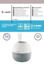
50195
Brand: JANE Pages: 40

Notus
Brand: Lanaform Pages: 88

1128
Brand: Lasko Pages: 2

Pure Comfort
Brand: OBH Nordica Pages: 40

HUMI-E D
Brand: S&P Pages: 28

CP70
Brand: UltraCOOL Pages: 2
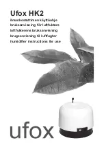
HK2
Brand: Ufox Pages: 24

LIMPIA 6
Brand: Olimpia splendid Pages: 52

roll NU10
Brand: Eldom Pages: 38

SEQUOIA
Brand: NATURE & DECOUVERTES Pages: 8

A04701
Brand: babymoov Pages: 60
Healthy Climate WB2-12
Brand: Lennox Pages: 8

Comfort SC-AH986M05
Brand: Scarlett Pages: 19


