background image


Precision Engineered Opto-Electronics

™ 


EX12LED 

Infrared LED Illuminator 


INSTALLATION INSTRUCTIONS

 
                                                                  MAN-12LED-06

Summary of Contents for EX12LED

Page 1: ...Precision Engineered Opto Electronics EX12LED Infrared LED Illuminator INSTALLATION INSTRUCTIONS MAN 12LED 06 ...

Page 2: ...cordance with manufacturer instructions 8 Do not install near any heat sources over manufacture specification temperature 9 Only use attachments accessories specified by the manufacturer 10 Refer all servicing to qualified service personnel Servicing is required when the apparatus has been damaged in a way such as the apparatus has been exposed to rain or moisture does not operate normally or has ...

Page 3: ...onform to all local codes EXTREME CCTV will not be responsible for injuries or damages resulting from the improper installation or use of any product sold by EXTREME CCTV their agents distributors or dealers EU Directives covered by this declaration 72 9 EC Low Voltage Directives 89 336 EEC Electromagnetic Compatibility Directive Le bloc d alimentation basse tension doit être conforme à la norme C...

Page 4: ...ver there is no guarantee that interference will not occur on a particular installation If the device does cause interference to radio or television reception the user is encouraged to try to correct the interference by one or more of the following measures 1 Fit Ferrite beads on all cable to and from the power supply box within the box walls 2 Route the composite cable between the camera and the ...

Page 5: ...on 2 Initial Preparations 3 Guidelines 3 Section 1 Mechanical Specifications 4 Section 2 Input Power Connections 7 Section 3 Mounting Illuminator Unit 8 Section 4 LED Adjustments 11 Section 5 Illuminator Re Assembly 13 Section 6 Troubleshooting Guide 15 Section 7 General Specifications 16 ...

Page 6: ...ted into a solid core CNC machined aluminum housing and beamed through a dark tinted tough window The EX12LED has an effective range up to 40 feet and is available in 850nm or 940nm with 30º or 60º beam spread A voltage regulator circuit allows for 12 24ac dc a range operation also providing protection from voltage surge transient spikes and reverse voltage The EX12LED is available in several mode...

Page 7: ...damaged in transit Contact BOSCH Service Center if a problem is noted see the rear page of this booklet for contact numbers PARTS LIST items supplied with unit EX12LED Unit including one U shaped mounting bracket with fasteners Installation Instructions booklet ITEMS REQUIRED FOR INSTALLATION Not supplied with unit Philips screwdriver Small slotted screwdriver Mounting screws etc ...

Page 8: ...ence Only Determine the optimum location for the Illuminator unit See Section 3 Mounting Illuminator Unit All units have been tested prior to shipment but it is advisable to check the unit s operation before installation GUIDELINES The installation and set up of the EX12LED is explained in Sections 3 and 4 It is important that these steps are followed in sequence ...

Page 9: ...4 1 MECHANICAL SPECIFICATIONS See Section 7 General Specifications for additional information FIGURE 1 1 Outline Dimensions ...

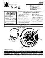
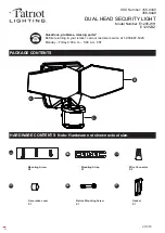
Page 10: ...5 FIGURE 1 2 Front View ...

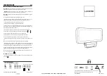
Page 11: ...6 FIGURE 1 3 Rear View ...

Page 12: ...7 2 INPUT POWER CONNECTIONS Reference Only The voltage operating range is 12 24AC DC Note input leads are not polarity dependent FIGURE 2 1 Voltage Regulator Board VRB LED Power Input VRB Power Input ...

Page 13: ...ee page 16 Ensure the selected location is protected from falling objects accidental contact with moving objects and unintentional interference from personnel Follow all applicable building codes The following installation guidelines must be followed Locate the camera such that it cannot be easily interfered with either intentionally or accidentally Select a mounting surface capable of supporting ...

Page 14: ...ket does not suit the needs of the installation the installer can utilize either of the two 20 camera mount holes located in the housing see Figure 1 3 on page 6 The choice of camera type mounting brackets is left to the installer Step 3 1 Mount the U bracket to the chosen mounting surface and attach the EX12LED with the supplied adjustment screws See Figure 3 1 on page 10 Step 3 2 Tighten the EX1...

Page 15: ...10 Note The Tilt Adjustment screws should be loosened only Do not remove these screws FIGURE 3 1 Mounting Details ...

Page 16: ... of LED is 0 9A by manufacturer default End user not advisable for adjustment For photocell On Off light level adjustment rotate VR2 Clockwise is off and counter clockwise is on FIGURE 4 1 LED and Photocell Adjustments Photocell On Off Adjustment ...

Page 17: ...ket attached to the rear cover plate has not been dislodged or warped Step 5 2 Gently press the rear cover into place making sure the gasket is properly seated and the photocell is centered in its viewing window See Figure 5 1 on page 14 Step 5 3 Attach the rear cover to the housing Step 5 4 Ensure the power cable has enough slack so that it is not stressed or crimped when the EX12LED unit is fixe...

Page 18: ...13 FIGURE 5 1 Rear Cover Re Assembly ...

Page 19: ... will have a faint red glow when ON 940nm LEDs are covert Aim the LEDs directly at an IR sensitive camera to see the lights or wait for the LEDs to warm up two minutes Feel for warmth LEDs are not ON Cover the photo sensor to activate power to the LEDs up to 30 seconds delay for activation Adjust the photocell s variable resistor towards the ON position Adjust power to the LEDs ...

Page 20: ...t light is present Make sure the photo sensor is not covered or hidden behind any object Check that the photocell is recessed in the viewing window Adjust the photocell s variable resistor towards the OFF position The LEDs will stay ON or OFF if the adjustments are at full turn ...

Page 21: ...30deg M Operational Range 20 C to 50 C 4 F to 122 F Humidity Range Up to 85 relative Power Supply 12V dc or 24V ac 60Hz 9W Viewing Window Acrylic Housing CNC Aluminum Anodized Dimensions W 2 875 73 0mm H 2 750 69 9mm D 2 750 69 9mm Weight 1 0 lbs 454g Subject To Change Without Notice ...

Page 22: ... Africa Bosch Security Systems B V P O Box 80002 5600 JB Eindhoven Netherlands Phone 31 40 2577 284 Fax 31 40 2577 330 emea securitysystems bosch com www boschsecurity com Asia Pacific Bosch Security Systems Pte Ltd 38C Japan Pemimpin Singapore 577 180 Phone 65 6319 3450 Fax 65 6319 3499 apr securitysystems bosch com www boschsecurity com Bosch Security Systems Inc 2009 Data subject to change with...

Reviews: