Bosch e-GoKart PowerTrain Young Star, Manual
The Bosch e-GoKart PowerTrain Young Star is an exciting electric go-kart designed for young racing enthusiasts. With its powerful engine and sleek design, this go-kart promises thrilling adventures. For a complete user experience, download the free manual from our website and get ready for non-stop fun!
Share
Download


Reviews:
No comments
Related manuals for e-GoKart PowerTrain Young Star
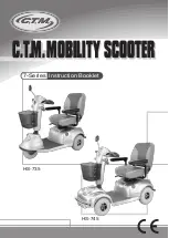
7 Series
Brand: C.T.M. Pages: 17
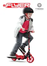
FLYER
Brand: Y Volution Pages: 36
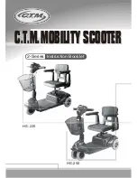
2 Series
Brand: C.T.M. Pages: 17
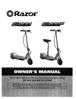
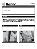
E200 Series
Brand: Razor Pages: 12
318
Brand: Rascal Pages: 39
99
Brand: LaScoota Pages: 10
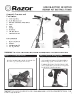
E300 Series
Brand: Razor Pages: 2
E300 Series
Brand: Razor Pages: 2
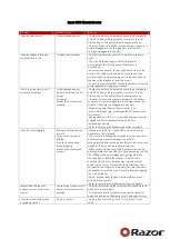
E300 Series
Brand: Razor Pages: 31
5 series
Brand: C.T.M. Pages: 18
SLATE
Brand: Jetson Pages: 20
Pro 8
Brand: W-Tec Pages: 19
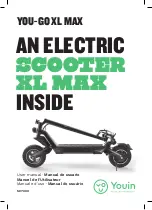
SC7000
Brand: Youin Pages: 80
V50
Brand: NAVEE Pages: 44
C25
Brand: Razor Pages: 2
EW-1000
Brand: E-Wheels Pages: 14
GS300
Brand: JDbug Pages: 8
Focus
Brand: KEEWAY Pages: 115


