background image

FLEXIDOME 5000 AN

VDN-5085

en

Installation Manual

Summary of Contents for DIVAR AN 5000

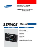
Page 1: ...FLEXIDOME 5000 AN VDN 5085 en Installation Manual ...

Page 2: ......

Page 3: ... 10 1 7 Bosch notice 10 2 Introduction 11 2 1 Features 11 3 Installation 12 3 1 Unpacking 12 3 2 Disassembly 13 3 3 Mounting the unit 14 3 3 1 Mounting tips 15 3 3 2 Flush mounting 15 3 3 3 Surface mounting 16 4 Connection and set up 19 4 1 Power and video connections 19 4 2 Setting up the camera 20 4 2 1 Camera positioning 20 4 2 2 Menu navigation 21 4 2 3 Focal length and focus 23 4 2 4 Heater 2...

Page 4: ... VMD submenu 37 5 5 7 Image Adjustment submenu 38 5 6 Install menu structure 39 5 6 1 Language submenu 40 5 6 2 Lens Wizard submenu 40 5 6 3 Synchronization submenu 41 5 6 4 Connections submenu 41 5 6 5 Test signal submenu 42 5 6 6 Camera ID submenu 42 5 6 7 Privacy masking submenu 44 5 6 8 Flip submenu 44 5 6 9 Defaults submenu 45 6 Troubleshooting 46 6 1 Resolving problems 46 6 2 Customer servic...

Page 5: ...uch as Dangerous Voltage inside the product If not avoided this will result in an electrical shock serious bodily injury or death WARNING Medium risk Indicates a potentially hazardous situation If not avoided this could result in minor or moderate bodily injury CAUTION Low risk Indicates a potentially hazardous situation If not avoided this could result in property damage or risk of damage to the ...

Page 6: ...utions to protect the unit from power and lightning surges 5 Controls adjustment Adjust only those controls specified in the operating instructions Improper adjustment of other controls may cause damage to the unit 6 Power sources Operate the unit only from the type of power source indicated on the label 7 Servicing Unless qualified do not attempt to service this unit yourself Refer all servicing ...

Page 7: ...ling an outdoor system extreme care should be taken to keep from touching power lines or circuits as this contact may be fatal U S A models only refer to the National Electrical Code Article 820 regarding installation of CATV systems 12 VDC 24 VAC power source This unit is intended to operate with a limited power source this power source must comply with EN60950 User supplied wiring from 12 VDC 24...

Page 8: ...hich have reached the end of their working life must be collected and disposed of separately from household waste material Separate collecting systems are usually in place for disused electronic and electrical products Please dispose of these units at an environmentally compatible recycling facility per European Directive 2002 96 EC CAUTION The Low Voltage power supply unit must comply with EN UL ...

Page 9: ...ermined by turning the equipment off and on the user is encouraged to try to correct the interference by one or more of the following measures reorient or relocate the receiving antenna increase the separation between the equipment and receiver connect the equipment into an outlet on a circuit different from that to which the receiver is connected consult the dealer or an experienced radio TV tech...

Page 10: ...outlined in UL s Standard s for Safety for Information Technology Equipment UL 60950 1 UL Certification does not cover the performance or reliability of the security or signaling aspects of this product UL MAKES NO REPRESENTATIONS WARRANTIES OR CERTIFICATIONS WHATSOEVER REGARDING THE PERFORMANCE OR RELIABILITY OF ANY SECURITY OR SIGNALING RELATED FUNCTIONS OF THIS PRODUCT 1 7 Bosch notice More inf...

Page 11: ... the high impact resistant polycarbon dome protect the camera module from damage The camera is easy to install and ready to use and offers the best solution for demanding scene conditions Features include 1 3 inch 960H CCD sensor with wide dynamic range True Day Night performance with switchable IR filter 720TVL sensor resolution High Dynamic Range Indoor and outdoor use IP66 and NEMA 4X compliant...

Page 12: ...ee SX8 4 5 6 mm mounting plugs and three matching mounting screws and special screwdriver bit for tamper resistant screws Plastic bag with two black rubber grommets for surface mount box Lens adjustment cap If equipment has been damaged during shipment repack it in the original packaging and notify the shipping agent or supplier WARNING Installation should only be performed by qualified service pe...

Page 13: ...lation Manual AM18 Q0648 v1 0 2013 03 3 2 Disassembly The flush mount version consists of the following parts The surface mount version consists of the following parts Figure 3 1 Flush mount Camera module and mounting base Inner liner with sealing ring Trim ring Dome ...

Page 14: ...nd dome by pulling them from the base 3 Remove the inner liner with sealing ring by pulling it off of the base 4 Remove the pink protective foam 3 3 Mounting the unit There are several ways to mount the unit The method of mounting depends on the type of surface and whether other mounting hardware such as an electrical box a surface box or other accessories are used Note Figure 3 2 Surface mount Su...

Page 15: ...the mounting hole template to assist in marking the correct position for the camera to be mounted Refer to the dimensions on the mounting hole template to find the exact position of the screw holes and the entry hole for the cables Partially screw in two screws for the keyholes and use them to temporarily hang the camera while the connections are made 3 3 2 Flush mounting Figure 3 3 Flush mounting...

Page 16: ...Release the two clips at the bottom of the watertight connection compartment to remove it from the mounting box Open the cover of the watertight compartment in the mounting box by releasing the five clips Run the power and video cables through separate rubber grommets into the watertight compartment Run the cable from the camera into the watertight compartment through the supplied grommet Make the...

Page 17: ...und cables of between 5 and 6 mm 0 2 0 24 inches for power and video connection Note Use some silicon spray on the cable to help slide the grommets onto it Figure 3 6 Surface mounting side connection 1 Solid surface pre drill three 8mm holes and fit supplied plugs 2 Three screws supplied with camera 3 Three screws M5 supplied 4 Integrated camera unit and base 5 Surface mounting box VDA 455SMB ...

Page 18: ...re 3 7 Surface mounting rear connection 6 Cables 7 Conduit 1 Solid surface three pre drilled 8mm holes and fit supplied plugs 2 Three screws supplied with camera 3 Three screws M5 supplied 4 Integrated camera unit and base 5 Surface mounting box VDA 455SMB 6 Cap remove for side entry cables 7 Conduit 8 Cables ...

Page 19: ...r 2 Partially insert two screws into the pre drilled holes or adapter plate 3 Using one of the keyholes hang the mounting base of the camera module on one screw temporarily tilt the base slightly to gain access to the cable connections 4 Connect the BNC connector of the camera module to the video coax cable 5 Connect the stripped power wires red brown to the power supply connector Note For a DC su...

Page 20: ...a composite video signal with sync An optional cable code number S1460 is available for making this connection When the S1460 cable is attached there is no video available on the BNC connector to avoid interference Figure 4 1 Camera parts CAUTION The Heater will be hot when in operation Do not touch Always switch the heater off when working on the camera refer to Section 4 2 4 Heater page 23 and S...

Page 21: ...ngs or sidewall mounting rotate the base of the lens along the twist axis C to align the picture shown on the monitor Do not rotate more than 340 For vertical adjustment along the tilt axis B loosen thumbwheels position camera then gently tighten thumbwheels to secure camera Do not rotate more than 90 4 2 2 Menu navigation Five keys located on the side panel are used for navigating through the men...

Page 22: ...o open the Install menu Use the up or down keys to scroll through a menu Use the left or right keys to move through options or to set parameters When in a menu quickly double press the menu select key to restore the selected item to its factory default To close all menus at once from any menu select the Exit item and hold down the menu select key until the menu display disappears Figure 4 2 Naviga...

Page 23: ...selection as the camera is now in a special mode for adjusting focus 3 To set the field of view of the varifocal lens loosen the focal length screw and turn the mechanism until the required view is displayed on the monitor Image goes out of focus 4 Focus the image on the monitor by loosening the focus screw and turning the mechanism until the image is in focus 5 Re adjust the focal length if neces...

Page 24: ...nner liner with attached sealing ring in position aligning its fin with the bracket on the base 2 Place the dome onto the base and rotate until it clips into place If necessary clean its surface with a soft cloth 3 Place the trim ring over the dome 4 Align the tamper resistant screws in the trim ring with the threaded ends in the mounting base 5 Use the special screwdriver bit supplied to tighten ...

Page 25: ... 1 Top level menus There are two upper level menus a Main menu and an Install menu The menus have functions that can be selected directly or submenus for more detailed set up To access the Main menu press the menu select button center for less than 1 second The Main menu appears on the monitor The Main menu allows you to select and set up the picture enhancement functions If you are not happy with...

Page 26: ... keys to move through options or to set parameters When in a menu quickly double press the menu select key to restore the selected item to its factory default To close all menus at once hold down the menu select key until the menu display disappears or continually select the Exit item Some menus automatically close after about two minutes other menus have to be closed manually Up button Menu Selec...

Page 27: ... settings are optimized for out of the box installation 2 Traffic Capture high speed objects using default shutter in variable lighting conditions 3 Low light Provide extra enhancement such as AGC and SensUp to make usable pictures in low light conditions 4 Smart BLC Settings optimized to capture details in high contrast and extremely bright dark conditions 5 Low noise Enhancements are set to redu...

Page 28: ... There are four different methods of controlling the IR filter via Bilinx communication automatically based on the observed light levels or as part of the programmable mode profile 5 4 Camera control communication Bilinx This camera is equipped with a coaxial communications transceiver also referred to as Bilinx In combination with VP CFGSFT the camera setting can be changed from any point along t...

Page 29: ...e Submenu Picture enhancement and performance Color Submenu White balance and color rendition VMD Submenu Video motion detection Image Adjustment Submenu Sets up digital zoom or digital image stabilization Item Selection Description Mode 1 to 6 Selects operating mode Mode ID Alphanumeric Mode name 11 characters maximum Copy active mode Available mode numbers Copies current mode settings to the mod...

Page 30: ...justs the speed of the video level control loop For most scenes it should remain at the default value Shutter AES FL Fixed AES auto shutter the camera automatically sets the optimum shutter speed FL flickerless mode avoids interference from light sources recommended for DC iris lenses only FIXED allows a user defined shutter speed Default AES shutter or Fixed shutter 1 50 PAL 1 60 NTSC 1 100 PAL 1...

Page 31: ... value Maximum AGC or Fixed AGC 0 to 40 dB Selects the maximum value the gain can have during AGC operation Selects the gain setting for Fixed gain operation 0 is no gain Actual AGC Displays the actual AGC value from the camera to help compare gain level with lighting levels and picture performance Sens Up Dynamic Off 2x 3x 10x Selects the factor by which the sensitivity of the camera is increased...

Page 32: ...h level 15 to 15 Sets the video level in Auto mode at which the camera switches to monochrome operation A low negative value means that the camera switches to monochrome at a lower light level A high positive value means that the camera switches to monochrome at a higher light level Switch delay 1 2 3 5 10 20 30 60 120 240 s Sets the evaluation time in Auto mode for day to night transitions Priori...

Page 33: ...e Normal the camera optimizes contrast in mono applications with visible light illumination IR illumination mono 0 to 15 Enter the strength of the external IR illumination to determine the night to day transition moment 0 is no IR illuminator 15 is very strong illumination Color burst mono On Off Off the color burst in the video signal is switched Off in monochrome mode On the color burst remains ...

Page 34: ...s pixels from each exposure are mixed to give a more detailed image Smart BLC BLC window and weighting factor are automatically defined Camera dynamically adjusts these for changing light conditions Contrast Enhancement Low Medium High Increases the contrast at medium brightness levels Select Low for high contrast scenes Select High for low contrast scenes e g fog Sharpness 15 to 15 Adjusts the sh...

Page 35: ...d of view or lowering the selection value 2D NR Off Low Medium High Automatically reduces the noise in the picture A high selection may cause blur A lower selection improves sharpness at the cost of more noise Peak White Invert On Off Use Peak White Invert to reduce glare from the CRT LCD display Use in ANPR LPR applications to reduce headlight glare Test on site to ensure that it does benefit the...

Page 36: ...production ATW hold Puts the ATW on hold and saves the color settings Manual the Red and Blue gain can be manually set to a desired position Speed Fast Medium Slow Adjusts the speed of the white balance control loop Red gain 50 to 50 Manual and ATW hold adjusts the Red gain Blue gain 50 to 50 Manual and ATW hold adjusts the Blue gain Saturation 15 to 5 Adjusts the color saturation 15 gives a monoc...

Page 37: ...he opposite corner which can now be moved Pressing Select again freezes the area and exits the area menu Item Selection Description VMD area Submenu Select 1 of the 4 areas to enter the area set up menu to define the detection area VMD mode Off Silent OSD Off Video Motion Detection VMD is off Silent video motion generates silent alarm OSD video motion generates on screen text message alarm VMD sen...

Page 38: ...8 Q0648 v1 0 2013 03 Installation Manual Bosch Security Systems 5 5 7 Image Adjustment submenu Item Selection Description Digital Zoom x1 x2 x4 x8 x16 Select the zoom factor DIS Off On Select On to stabilize the image EXIT Returns to main menu ...

Page 39: ...anguage Lens Wizard Submenu Select to optimize the focus point Synchroniza tion Submenu Sets synchronization parameters Connections Submenu Connection parameters Test signals Submenu Test patterns and texts Camera ID Submenu Select to access ID submenu Privacy masking Submenu Sets up a masking area Flip Submenu Selects flip submenu Default ALL Submenu Returns all settings for all modes to factory ...

Page 40: ...h Spanish French German Portuguese Russian Simplified Chinese Displays the menus on the OSD in the chosen language EXIT Returns to Install menu Item Selection Description Set focus now Select to fully open the iris Follow the instructions for adjusting the focus for the lens After focusing the object of interest remains in focus under bright and low light conditions EXIT Returns to Install menu ...

Page 41: ...ly frequency is detected EXIT Returns to Install menu Item Selection Description Heater Off Auto Select Auto to enable the thermostatically controlled heater function The heater switches on at approximately 0 C 32 F Bilinx Comms On Off If Off Bilinx communications is disabled Cable compensation Off Default RG59 RG6 Cable compensation is used to avoid the need for amplifiers in long distance coaxia...

Page 42: ...fault finding EXIT Returns to Install menu Item Selection Description Camera ID Enter a 17 character camera name Use Left Right to change position in the string use up down to select character Use Select to exit Display ID pos Off Top left Top right Bottom left Bottom right Select the screen position of the camera ID Camera ID border On Off Displays a grey border behind the camera ID to make it ea...

Page 43: ...ch Security Systems Installation Manual AM18 Q0648 v1 0 2013 03 Mode ID pos Off Top left Top right Bottom left Bottom right Camera mode is displayed on the screen in the selected position EXIT Returns to Install menu Item Selection Description ...

Page 44: ... moved with the Up Down Left Right arrow keys Pressing the Select key moves the flashing cursor to the opposite corner which can now be moved Pressing Select again freezes the area and exits the area menu 5 6 8 Flip submenu Item Selection Description Mask 1 to 15 15 different areas can be masked Pattern Black Grey White Noise Selects pattern for all masks Active On Off Turns each of the masks on o...

Page 45: ...ual AM18 Q0648 v1 0 2013 03 5 6 9 Defaults submenu Item Selection Description Restore All No Yes Restores all settings of the six modes to their default factory values Select YES then press the Menu Select button to restore all values When completed the message RESTORED is shown ...

Page 46: ...sible causes Solution No image transmission to remote location Defective camera Connect a local monitor to the camera and check the camera function Faulty cable connections Check all cables plugs contacts and connections Incorrect cable connections When using DC power ensure that polarity is correct No connection established no image transmission The unit s configuration Check all configuration pa...

Page 47: ...contact Bosch Security Systems Customer Service directly The Installer should write down all information regarding the unit so that it can be referenced for warranty or repair The version numbers of the firmware and other status information can be seen when the unit starts or by opening the Install menu Note down this information and the information found on the camera label before contacting cust...

Page 48: ...s that must be disposed of according to law Defective or superfluous devices and parts should be disposed of professionally or taken to your local collection point for hazardous materials CAUTION Never open the casing of the camera The unit does not contain any user serviceable parts Ensure that all maintenance or repair work is performed only by qualified personnel electrical engineering or netwo...

Page 49: ...nsor Maximum resolution 720TVL Rated supply voltage 12 VDC 24 VAC PAL 50 Hz NTSC 60 Hz SNR 54 dB Video output 1 Vpp 75 Ohm Synchroniza tion Internal Line Lock Shutter Auto 1 60 1 50 to 1 100000 Selectable fixed flickerless default Day Night Color Mono Auto Sens Up Adjustable from Off to 10x AGC AGC On or Off 0 40 dB selectable Dynamic engine XF Dynamic HDR Smart BLC Dynamic Range 94 dB Dynamic Noi...

Page 50: ... 16x Digital Image Stabilizer On Off Communication Two way Bilinx bi directional Languages OSD English Spanish French German Portuguese Russian Simplified Chinese Modes 6 programmable preset modes 24 hour Traffic Low light Smart BLC Low noise Vibrant Peak White Invert Suppresses highlights in scenes Power consumption 12 VDC 360 mA 700 mA with heater on 24 VDC 330 mA 650 mA with heater on Weight 75...

Page 51: ...ical Data en 51 Bosch Security Systems Installation Manual AM18 Q0648 v1 0 2013 03 8 1 1 Dimensions Figure 8 1 Dimensions Flush mount 57 6 2 27 57 6 2 27 158 6 22 39 5 1 56 85 3 35 33 3 1 31 66 5 2 62 1 2 1 4 7 7 95 3 7 mm in ...

Page 52: ... Technical Data FLEXIDOME 5000 AN AM18 Q0648 v1 0 2013 03 Installation Manual Bosch Security Systems Figure 8 2 Dimensions Surface mount 53 3 2 1 53 3 2 1 30 8 1 21 35 1 38 130 5 5 14 121 4 77 mm in 158 6 22 ...

Page 53: ...2013 03 8 1 2 Accessories BNC to UTP transceiver Surface Mount Box SMB Pendant wall mount Pendant ceiling mount Corner mount Bilinx communication interface box and software Contact a Bosch representative in your area for the latest available accessories or visit our website at www boschsecurity com ...

Page 54: ...54 en Technical Data FLEXIDOME 5000 AN AM18 Q0648 v1 0 2013 03 Installation Manual Bosch Security Systems ...

Page 55: ......

Page 56: ...Bosch Security Systems www boschsecurity com Bosch Security Systems 2013 ...

Reviews: