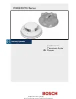
background image

D263/D273 Series

Installation Instructions 

Photoelectric Smoke 

EN 

Detector 

                    Available from A1 Security Cameras 

    www.a1securitycameras.com email: [email protected]

Summary of Contents for D263TH

Page 1: ...D263 D273 Series Installation Instructions Photoelectric Smoke EN Detector Available from A1 Security Cameras www a1securitycameras com email sales a1securitycameras com ...

Page 2: ...g systems refer to NFPA 72 For commercial and industrial installations space the detectors 30 ft 9 2 m apart as recommended by NFPA 72 An LED indicator flashes approximately every 3 5 sec to verify the detector has power and the smoke sampling circuitry is functioning The LED latches ON during an alarm allowing the user to easily verify individual detector alarms After you clear the alarm conditio...

Page 3: ...l injury and damage to the equipment The terminal block is removable It might be easier to remove the terminal block from the detector before making the wire connections Remove the terminal block by pulling it back and then pulling up Refer to Figures 3 through 8 on pages 3 through 5 for wiring details When all wiring connections are made connect the detector to the mounting plate by twisting it c...

Page 4: ...ut Voltage 10 to 30 VDC IN OUT IN OUT 5 6 7 8 Isolated Heat Output IN OUT IN OUT 9 10 Auxiliary Contact Normally Open 11 Black Yellow 24 V or Red 12 V Blue Blue 12 IN OUT IN OUT 1 3 4 1 Last detector 2 Control panel 3 EOL resistor 4 D275 EOL Power Supervision Module Figure 8 D273THR D273THSR Wiring Smoke Power Alarm Loop 1 2 3 4 5 6 7 8 Input Voltage 10 to 30 VDC IN OUT IN OUT Alarm Contacts Norma...

Page 5: ...e the detector for continuous operation Depending on local regulations calibration testing might be required more than once a year NFPA 72 recommends calibration testing at installation and then every other year Perform a Functional Test annually Test the detector s sensitivity to meet NFPA 72 requirements by conducting a Magnet Test or measuring the calibration voltage pins with a D1005 Test Cabl...

Page 6: ...m Before proceeding to the next detector clear each alarm for every test 5 0 Maintenance At least once a year clean the detector Pay particular attention to the screens when cleaning the detector In dusty areas or areas of heavy insect concentration you might need to clean the screens more often Unlatch and pry the cover away from the chassis Refer to Items 1 through 3 in Figure 9 1 Grasp the cham...

Page 7: ...Series Models Model Circuit Type 135 F 57 C Heat Sensor 85 dB Sounder Trouble Relay EOL Relay Auxiliary Relay Current Draw Standby Alarm D263 Two wire 100 µA maximum Determined by control panel D263TH Two wire X 100 µA maximum Determined by control panel D263THC Two wire X X 100 µA maximum Determined by control panel D263THS Two wire X X 100 µA maximum Determined by control panel D273 Four wire 10...

Page 8: ... Perinton Parkway Fairport NY 14450 9199 Customer Service 800 289 0096 Technical Support 888 886 6189 2006 Bosch Security Systems 31341J Available from A1 Security Cameras www a1securitycameras com email sales a1securitycameras com ...

Reviews: