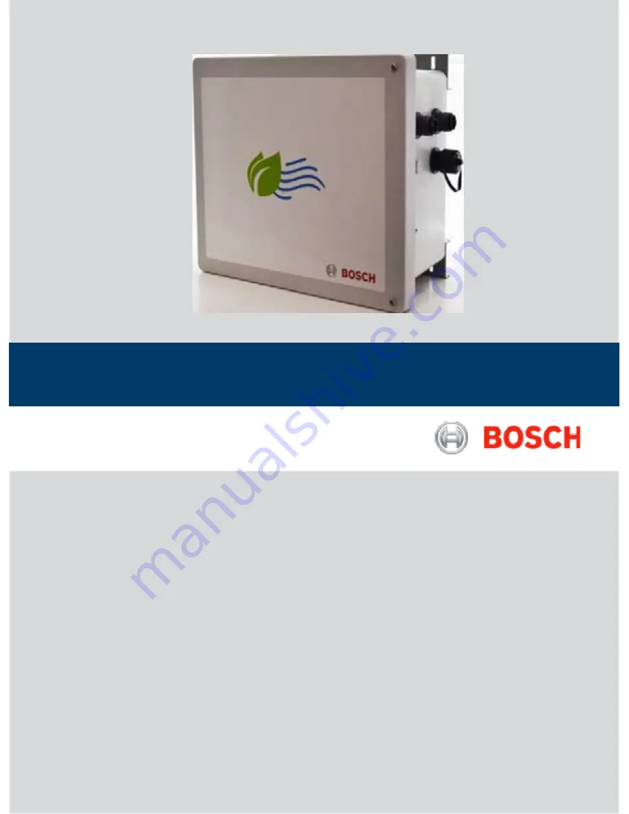
background image

Micro Climate Monitoring System 

BOSCH CLIMO 

Summary of Contents for CLIMO A D00 A40 103

Page 1: ...MicroClimateMonitoringSystem BOSCH CLIMO ...

Page 2: ... CLIMO overview 6 2 1 Version of product 6 11 FCC Warningstatement 15 105 17 2 2 Applications 6 2 3 Site Parameter selection as per CPCB guidelines on measurement of Ambient Air 12 Statement 17 Pollutants Air Quality 6 2 4 Device specifications 7 13 Mobile Device 17 2 5 Technical data 8 14 RED Requirement 17 3 Pre Installation 9 3 1 Installation Kit 9 3 2 Tools 9 3 3 Torque table 9 3 4 SIM inserti...

Page 3: ...00mm all round the unit Do not place objects filled with liquids such as vases or cups on the unit Never spill liquid of any kind on the unit Donotopenthe mating connectorand dustcap inrainy 1 2 Symbols in this documentation Symbol Designation Explanation Attention Warns about possible property damage i Information Practical hints and other useful information 1 2 Multi step operation Instruction c...

Page 4: ...ranty Do not try to extract screw break or move connectors far from necessary usage waterproof sealing can be damaged and warranty will be voided Do not connect any sensor not provided by RBEI Do not place nodes on places or equipment where it could be exposed to shocks and or big vibrations Do not keep mating connectors or dust caps in unlock condition Do not use dropped unit Do notreplace the se...

Page 5: ...e covers are to be placed at 180 with bottom support Don ts Do not rest enclosure cover on vent kits Do not rest enclosure itself on vent kit 1 7 Short information Alleffortshave beenmade toensuretheaccuracyofmaterialprovidedin thisdocumentatthe time ofrelease However the items described in this document are subject to continuous development and improvement All specifications are subjected to chan...

Page 6: ...variation in sensor behavior due to limitation of NO NO2 and O3 sensors on higher temperature range beyond 40 C and PM sensor for below 10 C 2 2 Applications Real Estate and Community BOSCH CLIMO will be the indicator for quality of life index and the breathability of the ambient air The recommendations and early warning system based on air profiling will help the society to make smarter choices S...

Page 7: ...ing and Business Solutions Private Limited 2 4 Device specifications This section shows the overall dimensions of the BOSCH CLIMO design Detailed installation steps are explained in further sections Fig 1 Mounting envelope BOSCH CLIMO overview 7 en ...

Page 8: ...s and shock protection Power supply 100VAC 240VAC 50 60 Hz or 9 12 V DC Maximum power rating 20W Ambient Operating Temperature 20 C 50 C Humidity 15 85 RH Enclosure UV stabilized industrial housing molded fiberglass reinforced polyester Color RAL 7035 light gray System weight 6 kgs Dimension L x W x H L 30cm x W 25cm x H 15cm Compact housing Certifications 3G Ethernet version CE and FCC certified ...

Page 9: ...ectors i Refer to the Connector website for installation of Ethernet cable with Ethernet mounting connector i MatingconnectorisnotpartofBOSCHCLIMOunit It is recommended to use IP65 compliant mating connectorsmentionedinthetablebelow Mating connector Mfr Part Number Description Ethernet Conec 17 10001 Plug modular connector 8p8c RJ45 Ethernet position shielded Cat5e IDC USB Conec 17 200121 USB A US...

Page 10: ...cles 3 8 Health indicators You can know the device is functional by checking the red LED indicator Blinking of this LED indicates that there is a proper connection of the BOSCH CLIMO device with cloud and the data is being transmitted successfully 3 9 Pre installation Acceptance checklist iTake the print out of the checklists sign and store it for every unit Sl No Description Test Passed Yes No NA...

Page 11: ...lash guard CO2 Sensor assembly UV sensor assembly Solar Shade 2 Ensure mating connectors and dust caps should be in locked condition 3 Connection details Ethernet 3G 4 Switch on the unit and observe blinking of the red LED 5 Ensure the device updating the data on the cloud verified by customer using their system 6 Picture of installation in four direction 7 Details of the four direction at the loc...

Page 12: ...tallation kit 4 Check the delivery carefully to make sure that all parts have been delivered If there is any mistake please contact your authorized dealer atonce Fig 2 Packaging i Intheinstallationkit partsforbothwallmountingand pole mounting are available i Keep the original package for the future transporting 4 2 Installing SIM To install SIM in the unit Ensure to take necessary ESD precautions ...

Page 13: ...ed as space is required to fix the screw through the mounting bracket 1 Fix the UV sensor on the sun shade from bottom first 4 5 Wall mounting To wall mount the unit 1 Use the wall mounting template to mark out the four mounting holeson the wall 2 Drill holes on the marked points of the wall i The mounting holes should be such that it can accommodate the proposed wall plugs and screws 3 Insert the...

Page 14: ...not a load carrying componentand can cause damage Do not rest the unit on splash guard i While assembling handle CO2 sensorwithcareand avoid installing any other equipment around the sensor Fig 8 Splash guard with CO2 sensor 4 8 ACDCconnection To connect AC or DC cable to the unit 1 When the unit is assembled either on pole orwall check that the unit is in perfect condition and without anydamage 2...

Page 15: ...he range and associated health risks for each category are as follows AQI category Range Associated health impacts Good 0 50 Minimal impact Satisfactory 51 100 May cause minor breathing discomfort to sensitive people Moderately polluted 101 200 May cause breathing discomfort to people with lung disease such as asthma and discomfort to people with heart disease children and older adults Poor 201 30...

Page 16: ... faced to south north if you are on the south hemisphere and tilted 45º Always place the unit such that the connectors and antenna face towards either to west or east Keep the unit out of range of people who can damage installation wet sensors etc As per sensor manufacturer s specification sensors are capable of producing accurate data under stable temperature humidity The standard test conditions...

Page 17: ...mmunications However there is no guarantee that interference will not occur in a particular installation If this equipment does cause harmful interference to radio or television reception which can be determined by turning the equipment off and on the user is encouraged to try to correct the interference by one or more of the following measures Reorient or relocate the receiving antenna Increase t...

Page 18: ...Robert Bosch Engineering and Business Solutions Private Limited 123 Industrial Layout Hosur Road Koramangala Bangalore 560 095 INDIA ...

Reviews: