Bosch CCS800, Service Manual
The Bosch CCS800 Service Manual is a comprehensive resource that provides detailed instructions and information for users of the Bosch CCS800 system. This manual is available for free download on our website, ensuring easy access to the valuable knowledge needed to optimize the performance of your Bosch CCS800 product.
Share
Download


Reviews:
No comments
Related manuals for CCS800
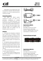
DM-50
Brand: GATT AUDIO Pages: 2
ICON
Brand: Earthworks Audio Pages: 3

LM10
Brand: Samson Pages: 24
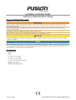
FUSION
Brand: Garmin Pages: 8
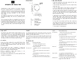
GP3
Brand: IASUS Pages: 2
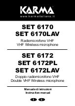
6170
Brand: Karma Pages: 12
AG-MC15P
Brand: Panasonic Pages: 12
WV-SMR10
Brand: Panasonic Pages: 20
Q1
Brand: Samson Pages: 4
P30
Brand: Earthworks Pages: 2
TC25
Brand: Earthworks Pages: 2
SMART
Brand: Hama Pages: 78
Net Mic
Brand: 2N Pages: 4
BM100
Brand: Uniden Pages: 2
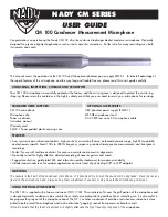
CM 100
Brand: Nady Systems Pages: 2
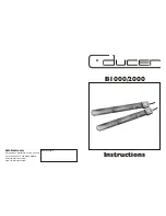
B1000
Brand: C-ducer Pages: 4
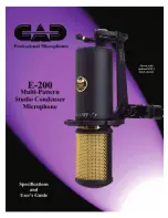
E-200
Brand: CAD Pages: 4
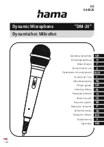
DM-20
Brand: Hama Pages: 38


