Bosch Carephone 62 CRS-H62M-GB, User Manual
The Bosch Carephone 62 CRS-H62M-GB is a versatile personal care phone designed to enhance safety and convenience. With its user-friendly features and intuitive interface, this product ensures easy operation. Explore its capabilities further by downloading the free user manual from manualshive.com to understand all its functionalities.
Share
Download


Reviews:
No comments
Related manuals for Carephone 62 CRS-H62M-GB
SL3000
Brand: Safeline Pages: 32
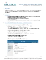
VOIP-500 Series
Brand: Talkaphone Pages: 4
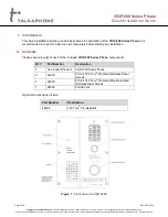
VOIP-500 Series
Brand: Talkaphone Pages: 6
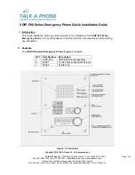
VOIP-600 Series
Brand: Talk-a-Phone Pages: 6
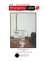
10-4
Brand: United Security Products Pages: 24
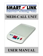
MEDI-CALL UNIT
Brand: Smartlink Pages: 8
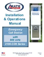
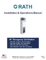
Dusk2Dawn 2100-CD9 Series
Brand: Rath Pages: 8
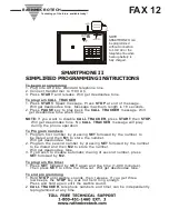
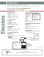
SMARTPHONE II
Brand: RATH MICROTECH Pages: 2
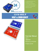
GSM-HELP
Brand: Wafer Microelectronics Pages: 6
SMARTPHONE III
Brand: RATH MICROTECH Pages: 2
2100-CPL
Brand: Rath Pages: 9
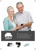
Grey bell
Brand: sabya Pages: 27
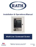
Multi-Line Command Center
Brand: Rath Pages: 11
2100-CD9
Brand: Rath Pages: 9
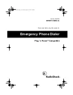
Emergency Phone Dialer
Brand: Radio Shack Pages: 20
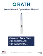
2100-TLL Landline 12v Tower
Brand: Rath Pages: 9
DIAL-ALERT AD-105 Guide
Brand: SkyLink Pages: 14
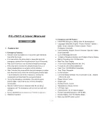
FC-7677-2
Brand: FutureCall Pages: 11


