Bosch Carephone 61, User Manual
The Bosch Carephone 61, a reliable and user-friendly emergency communication device, is here to provide peace of mind. Ensure you have all the necessary information at your fingertips with our comprehensive User Manual. Download it for free from our website and discover the full potential of this exceptional product.
Share
Download


Reviews:
No comments
Related manuals for Carephone 61
SL3000
Brand: Safeline Pages: 32
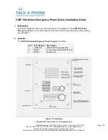
VOIP-500 Series
Brand: Talkaphone Pages: 4
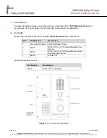
VOIP-500 Series
Brand: Talkaphone Pages: 6
VOIP-600 Series
Brand: Talk-a-Phone Pages: 6
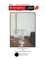
10-4
Brand: United Security Products Pages: 24
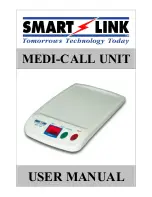
MEDI-CALL UNIT
Brand: Smartlink Pages: 8
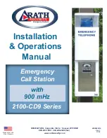
Dusk2Dawn 2100-CD9 Series
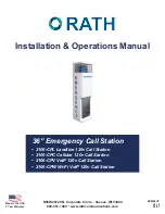
Brand: Rath Pages: 8
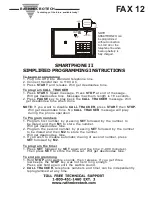
SMARTPHONE II
Brand: RATH MICROTECH Pages: 2
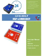
GSM-HELP
Brand: Wafer Microelectronics Pages: 6
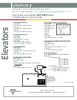
SMARTPHONE III
Brand: RATH MICROTECH Pages: 2
2100-CPL
Brand: Rath Pages: 9

Grey bell
Brand: sabya Pages: 27
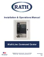
Multi-Line Command Center
Brand: Rath Pages: 11
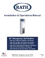
2100-CD9
Brand: Rath Pages: 9
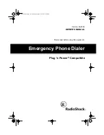
Emergency Phone Dialer
Brand: Radio Shack Pages: 20
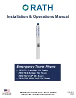
2100-TLL Landline 12v Tower
Brand: Rath Pages: 9
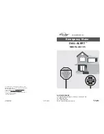
DIAL-ALERT AD-105 Guide
Brand: SkyLink Pages: 14
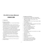
FC-7677-2
Brand: FutureCall Pages: 11


