

Summary of Contents for Carephone 52+
Page 1: ...en Operating Manual Carephone 52 ...
Page 2: ......
Page 51: ...Carephone 52 Appendix en 51 Bosch Security Systems Operating Manual F 01U 031 884 V4 2009 03 ...
Page 52: ......
Page 53: ......
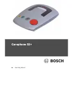
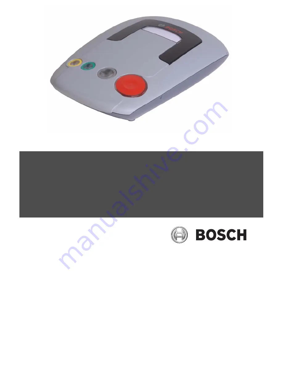
The Bosch Carephone 52+ is a reliable and user-friendly personal emergency response system. Stay connected and ensure peace of mind with this advanced device. Access the comprehensive Operating Manual for free, available for download from our website. Discover how to use this product and enjoy its features worry-free.
Page 1: ...en Operating Manual Carephone 52 ...
Page 2: ......
Page 51: ...Carephone 52 Appendix en 51 Bosch Security Systems Operating Manual F 01U 031 884 V4 2009 03 ...
Page 52: ......
Page 53: ......