Bosch Carephone 50 ISA-50-MS, User And Programming Manua
The Bosch Carephone 50 ISA-50-MS is a user-friendly and reliable personal emergency response system. Stay connected and well-equipped with the comprehensive User and Programming Manual. Download the manual for free from our website, ensuring that you have all the necessary information to operate and customize this excellent product.
Share
Download


Reviews:
No comments
Related manuals for Carephone 50 ISA-50-MS
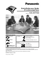
VoiceSonic KX-NT700
Brand: Panasonic Pages: 8
S850i
Brand: Aastra Pages: 22
V10
Brand: Accutone Pages: 10
PJP-100UH
Brand: Yamaha Pages: 3
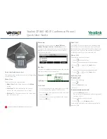
CP860 SERIES
Brand: Yealink Pages: 5
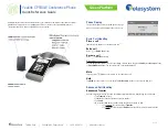
CP930W Telesystem
Brand: Yealink Pages: 2
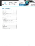
One Talk CP960
Brand: Yealink Pages: 4
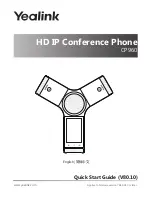
One Talk CP960
Brand: Yealink Pages: 20
CP935W
Brand: Yealink Pages: 8
CX300
Brand: Polycom Pages: 36

Multicom
Brand: Albrecht Pages: 52
iMeet
Brand: Dolby Laboratories Pages: 31
SoundStation 7000
Brand: Polycom Pages: 38

Feb-74
Brand: GE Pages: 40
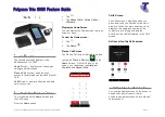
realpresence trio 8800
Brand: Polycom Pages: 7
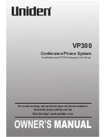
VP300
Brand: Uniden Pages: 141
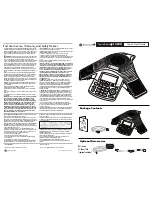
SoundStation 1725-30955-001
Brand: Polycom Pages: 2
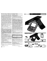
1725-15849-001
Brand: Polycom Pages: 2


