

3 | Installation
2.1 | Access the address switches
1 | Overview
Caution!
Remove all power (AC and battery) before making any
connections. Failure to do so might result in personal
injury and/or equipment damage.
5 | Status indicators
Status
indicator
Function
Ready to turn on (arm)
Turned on (armed)
GAS
Gas alarm
AC (Mains) power present
Fire keypad
indicator
Function
Fire alarm
Silenced
Supervisory condition
System trouble
Adjusting nightlight (for control panels with version 2.01 or
higher):
1. Press [MENU] or press [CMD][8] to open the Main menu.
2. Use [NEXT] to go to the Press 5 for Settings Menu option,
or simply press [5].
3. Use [NEXT] to go to the Press 4 for Keypad Config
option,
or simply press [4].
4. Use [NEXT] to go to the Press 4 for Nightlight
option, or
simply press [4].
5. Use [PREV] or [NEXT] to toggle between the Yes and No
options.
6. Press [ENTER] while viewing the desired option to save the
programming.
7. Press [ESC] to exit the menu.
Adjusting the brightness:
1. Press [MENU] or press [CMD][8] to open the Main menu.
2. Use [NEXT] to go to the Press 5 for Settings Menu option,
or simply press [5].
3. Use [NEXT] to go to the Press 4 for Keypad Config
option,
or simply press [4].
4. Press [1] to adjust the brightness.
5. Use [PREV] or [NEXT] to adjust the brightness level. The
changes apply immediately.
6. Press [ESC] to exit the menu.
4 | Display
3.1 | Install the keypad
3.2 | Attaching to the control panel
You can surface install the keypad, or install it to standard
electrical boxes, including single gang boxes.
1. Use the base as a template to mark surface.
2. Pull the wiring through the opening in the base.
3. Use the mounting hardware to attach.
Use the control panel terminals labeled R, Y, G, B (PWR, A, B,
COM). Connect them to the keypad terminals labeled R, Y, G, B.
Keypads can be wired directly to the control panel or from
keypad to keypad.
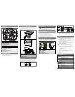
Callout ― Description
1 ― Control panel
2 ― Terminal wiring
3 ― Keypad’s wiring terminal block
1
2
3
R
Y
G
B
SDI2
PWR+/R
A/Y
B/G
COM/B
27
28
29
26
e
SDI2
PWR+/R
A/Y
B/G
COM/B
28
29
30
27
e
Reconnect the keypad to the base by sliding the keypad onto
the base (reverse of
Step 2
). Apply power to the system.
SDI2
PWR+/R
A/Y
B/G
COM/B
27
28
29
26
e
SDI2
PWR+/R
A/Y
B/G
COM/B
28
29
30
27
e
R
Y
G
B
2 | SDI2 address switches
Two switches set the address for the keypad. The control panel
uses the address for communication.
GAS
GAS
Set the address switches per the control panel configuration.
Each SDI2 keypad must have a unique address. For single-
digit addresses 1 through 9, set the tens switch to 0. The
following illustration shows the address switch setting for
address 1.
Callout ― Description
1 ― Address switches
1
2.2 | Setting the address switches
1. Use a slotted screwdriver. Turn the lock counter-
clockwise.
2. Push down on the keypad to remove it from the base.
3. Find the switches on the back of the keypad.
Refer to the following illustrations.
1
2
This keypad is an SDI2 bus compatible
Callout ― Description
1 ― Wall mount holes
2 ― Single gang box holes
3 ― Double gang box holes
4 ― Wire opening
5 ― Surface mount wire openings
6 ― Gang box holes (3-4 in)
7 ― Surface mount wire channel
8 ― Bubble level
9 ― SDI2 wiring terminal block
10 ― Wire tie posts
R Y G B
6
2
4
9
1
2
3
3
7
7
5
5
1
1
10
6
6
5
8
10
10


