

Refer to the following table.
3 | LED descriptions
Use Remote Programming Software
(RPS) or an SDI2 keypad to program.
For programming parameter
descriptions, options, and defaults refer
to
RPS Help
or the
Program Entry Guide
for your control panel.
4 | Configuration
Flash pattern
Function
OFF Steady
Standby
ON Steady
Line seize
Flash
Ring detect
2.2 | Wire the module
1. Insert the support leg into the support hole labeled X.
2. Align the PCB metal contacts with the on-board connector.
3. Push the module into place until it is tight.
Callout ― Description
Callout ― Description
1 ― Support leg
3 ― Plug-in module retention clip
2 ― PCB metal contacts
1. Connect one end of a telephone
cord to the B430.
2. Connect the other end to an
RJ31X or RJ38X phone jack. The
module has pads on both sides of
the board to connect a telephone
test set. Refer to the following
illustration.
Callout ― Description
1 ― Premises telephone
2 ― Incoming Telco line
3 ― Installer telephone test set
4 ― RJ45 phone connector
The B430 connects to the control panel for communication over the PSTN (Public
Switched Telephone Network).
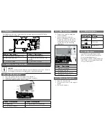
Callout ― Description
Callout ― Description
1 ― Module handle and support leg
4 ― RJ45 phone connector
2 ― Line seize/ring LED
5 ― Plug-in module retention clip
opening
3 ― Test phone pads
6 ― PCB metal contacts
NOTICE!
Remove all power (AC and battery) before making any connections. Failure to
do so might result in personal injury and/or equipment damage.
2 | Install or remove the module
2.1 | Install the module
1 | Overview
1. Open the retention clip.
2. Hold the top corners of the support
handle.
3. Pull out the module.
2.3 | Remove the module
1
2
3
4
5
6
1


